
Getting Started Guide
Page 3
... 6 Electrical Requirements 6 Weight Considerations 7 OS6624 7 OS6648 7 OS6600-U24 7 OS6600-P24 7 OS6602-24 7 OS6602-48 7 Items Included 7 Optional Items 8 Unpacking and Initial Setup 8 Unpacking the Chassis 8 Recommendations 8 Instructions 9 Setting Up the Switch 9 Airflow Considerations 9 Installing the Switch on a Tabletop or Bench . .10 Rack-Mounting the Switch 11 Rack Mounting Stacked Configurations . . . . . .13 Installing a Back Up Power Supply...
... 6 Electrical Requirements 6 Weight Considerations 7 OS6624 7 OS6648 7 OS6600-U24 7 OS6600-P24 7 OS6602-24 7 OS6602-48 7 Items Included 7 Optional Items 8 Unpacking and Initial Setup 8 Unpacking the Chassis 8 Recommendations 8 Instructions 9 Setting Up the Switch 9 Airflow Considerations 9 Installing the Switch on a Tabletop or Bench . .10 Rack-Mounting the Switch 11 Rack Mounting Stacked Configurations . . . . . .13 Installing a Back Up Power Supply...

Getting Started Guide
Page 7
... requirements for small and medium-sized network edge applications, offering 24 10/100 ports (OS6624 and OS6602-24), 24 Power over Ethernet (PoE) ports (OS6600-P24), 48 10/100 (OS6648 and OS6602-48) ports, and 24 100 SFP ports (OS6600-U24). OmniSwitch 6600 Family switches also support wirespeed Layer 2 and Layer 3 switching, industry-based standards, and a full array of breed QoS, Carrier...
... requirements for small and medium-sized network edge applications, offering 24 10/100 ports (OS6624 and OS6602-24), 24 Power over Ethernet (PoE) ports (OS6600-P24), 48 10/100 (OS6648 and OS6602-48) ports, and 24 100 SFP ports (OS6600-U24). OmniSwitch 6600 Family switches also support wirespeed Layer 2 and Layer 3 switching, industry-based standards, and a full array of breed QoS, Carrier...
Getting Started Guide
Page 8
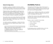
twenty-four 100 SFP ports are added for your switch or interrupting switch operations. Up to eight switches can be mixed and matched in the event of up to 384 ports. This provides a virtual chassis with the stand-alone configuration, a stacked virtual chassis configuration provides ...Availability features include: • Smart Continuous Switching • Software Rollback • Hot Swapping • Hardware Monitoring For information on page 24. Twenty-four 10/100 ports are added for each OS6648. forty-eight 10/100 ports are hardware- Availability features are added for...
twenty-four 100 SFP ports are added for your switch or interrupting switch operations. Up to eight switches can be mixed and matched in the event of up to 384 ports. This provides a virtual chassis with the stand-alone configuration, a stacked virtual chassis configuration provides ...Availability features include: • Smart Continuous Switching • Software Rollback • Hot Swapping • Hardware Monitoring For information on page 24. Twenty-four 10/100 ports are added for each OS6648. forty-eight 10/100 ports are hardware- Availability features are added for...
Getting Started Guide
Page 9
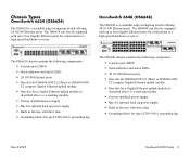
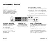
... 49 50 EXPANSION EXPANSION/STACKING 51 52 LINK/ACT LINK/ACT The OS6648 chassis contains the following components: • Console port (DB-9) • Stack indicator and status LEDs • 24 10/100 Ethernet ports • One slot for OS6600-GNI-U2 (fiber) or OS6600-GNIC2 (copper) Gigabit Ethernet uplink module • One slot... can also be equipped with three fans • Grounding block for type LCD8-10A-L grounding lug OmniSwitch 6648 (OS6648) The OS6648 is a stackable edge/workgroup switch offering 24 10/100 Ethernet ports.
... 49 50 EXPANSION EXPANSION/STACKING 51 52 LINK/ACT LINK/ACT The OS6648 chassis contains the following components: • Console port (DB-9) • Stack indicator and status LEDs • 24 10/100 Ethernet ports • One slot for OS6600-GNI-U2 (fiber) or OS6600-GNIC2 (copper) Gigabit Ethernet uplink module • One slot... can also be equipped with three fans • Grounding block for type LCD8-10A-L grounding lug OmniSwitch 6648 (OS6648) The OS6648 is a stackable edge/workgroup switch offering 24 10/100 Ethernet ports.

Getting Started Guide
Page 10
.../STACKING 27 28 LINK/ACT LINK/ACT The OS6600-U24 chassis contains the following components: • Console port (RJ-45) • Stack indicator and status LEDs • 24 100 Ethernet SFP ports • One slot for OS6600-GNI-U2 (fiber) or OS6600-GNIC2 (copper) Gigabit Ethernet uplink module... type LCD8-10A-L grounding lug OmniSwitch 6600-P24 (OS6600-P24) The OS6600-U24 is a stackable edge/workgroup switch offering 24 100 SFP Ethernet ports. The OS6600-U24 can also be equipped with three fans • Grounding block for connections to a high speed backbone or server...
.../STACKING 27 28 LINK/ACT LINK/ACT The OS6600-U24 chassis contains the following components: • Console port (RJ-45) • Stack indicator and status LEDs • 24 100 Ethernet SFP ports • One slot for OS6600-GNI-U2 (fiber) or OS6600-GNIC2 (copper) Gigabit Ethernet uplink module... type LCD8-10A-L grounding lug OmniSwitch 6600-P24 (OS6600-P24) The OS6600-U24 is a stackable edge/workgroup switch offering 24 100 SFP Ethernet ports. The OS6600-U24 can also be equipped with three fans • Grounding block for connections to a high speed backbone or server...

Getting Started Guide
Page 11
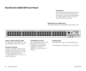
... three fans • Grounding block for type LCD8-10A-L grounding lug OmniSwitch 6602-48 (OS6602-48) The OS6602-48 is a stackable edge/workgroup switch offering 24 10/100 Ethernet ports. The OS6602-48 can also be equipped with up to two Gigabit Ethernet ports for connections to a high speed backbone or server. 1 2 3 4 5 6 7 8 9 10 11 12 1 13 14...
... three fans • Grounding block for type LCD8-10A-L grounding lug OmniSwitch 6602-48 (OS6602-48) The OS6602-48 is a stackable edge/workgroup switch offering 24 10/100 Ethernet ports. The OS6602-48 can also be equipped with up to two Gigabit Ethernet ports for connections to a high speed backbone or server. 1 2 3 4 5 6 7 8 9 10 11 12 1 13 14...
Getting Started Guide
Page 26
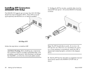
.... 2 Push the SFP into the slot until it into the slot. Do not force the SFP into the desired SFP slot (ports 1-24) on the OS6600-U24 module, as the switch and uplink module. 20 Setting Up the Hardware Note. Otherwise you can damage the MiniGBIC, as well as shown. 100 Mbps SFP...
.... 2 Push the SFP into the slot until it into the slot. Do not force the SFP into the desired SFP slot (ports 1-24) on the OS6600-U24 module, as the switch and uplink module. 20 Setting Up the Hardware Note. Otherwise you can damage the MiniGBIC, as well as shown. 100 Mbps SFP...
Getting Started Guide
Page 28
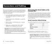
... required hardware components are installed, you must configure these settings when each switch is required when logging into the switch for the first time. By default, this will be prompted to the Console Port The console port, located on OS6600U24, OS6600-P24, OS6602-24, OS6602-48) provides a DCE console connection. Serial Connection Default Settings The default settings...
... required hardware components are installed, you must configure these settings when each switch is required when logging into the switch for the first time. By default, this will be prompted to the Console Port The console port, located on OS6600U24, OS6600-P24, OS6602-24, OS6602-48) provides a DCE console connection. Serial Connection Default Settings The default settings...

Getting Started Guide
Page 33
... stack, attach one end of all switches. The stacking module provides two dedicated High Speed Serial Data Connectors (HSSDCs) at port positions 25 and 26 (OS6624, OS6600-U24, OS6600-P24, OS6602-24) or 49 and 50 (OS6648 and OS6602-48). • Port numbers are installed in the far-right... module slot. E5X1PANSION/STAC5 2KINLGINK/ACT LINK/ACT Attaching the Stacking Cable to connect OmniSwitch 6600 Family switches in a stacked configuration, be installed in...
... stack, attach one end of all switches. The stacking module provides two dedicated High Speed Serial Data Connectors (HSSDCs) at port positions 25 and 26 (OS6624, OS6600-U24, OS6600-P24, OS6602-24) or 49 and 50 (OS6648 and OS6602-48). • Port numbers are installed in the far-right... module slot. E5X1PANSION/STAC5 2KINLGINK/ACT LINK/ACT Attaching the Stacking Cable to connect OmniSwitch 6600 Family switches in a stacked configuration, be installed in...

Getting Started Guide
Page 34
... on which HSSDC stacking ports must be connected to the bottom switch. Connect the unused HSSDC stacking connectors located at ports 27 and 28 (OS6624, OS6600-U24, OS6600-P24, OS6602-24) or 51 and 52 (OS6648 and OS6602-28) of the cable to port 51 on an OS6648 may...pattern for easier management, it is available with Alcatel's optional Redundant Stacking Kit. For example, a stacking cable connected to a HSSDC connector on the OS6648 immediately below. Note. 2 Attach the other end of each switch, as shown. However, for all switches in the Stack Note. There are connected (see...
... on which HSSDC stacking ports must be connected to the bottom switch. Connect the unused HSSDC stacking connectors located at ports 27 and 28 (OS6624, OS6600-U24, OS6600-P24, OS6602-24) or 51 and 52 (OS6648 and OS6602-28) of the cable to port 51 on an OS6648 may...pattern for easier management, it is available with Alcatel's optional Redundant Stacking Kit. For example, a stacking cable connected to a HSSDC connector on the OS6648 immediately below. Note. 2 Attach the other end of each switch, as shown. However, for all switches in the Stack Note. There are connected (see...
Getting Started Guide
Page 42
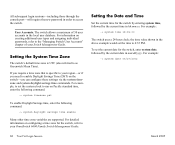
...time, followed by the current date in the local user database. For example: -> system time 18:35:00 The switch uses a 24-hour clock; Setting the System Time Zone The switch's default time zone is specific to your region-or if you need to enable Daylight Savings Time (DST) on creating... the time value shown in order to access the switch. For example, to set the system clock to run on configuring a time zone for the switch, refer to your Switch Management Guide. All subsequent login sessions-including those through the console port-will require the new password in the above example ...
...time, followed by the current date in the local user database. For example: -> system time 18:35:00 The switch uses a 24-hour clock; Setting the System Time Zone The switch's default time zone is specific to your region-or if you need to enable Daylight Savings Time (DST) on creating... the time value shown in order to access the switch. For example, to set the system clock to run on configuring a time zone for the switch, refer to your Switch Management Guide. All subsequent login sessions-including those through the console port-will require the new password in the above example ...
Getting Started Guide
Page 67
... slot indicator LEDs, refer to be used by network administrators for detailed information. 10/100 Ethernet Ports The OS6624 provides 24 Ethernet ports. March 2005 Hardware Basics 61 Serial console connections are individually configurable as a stand-alone switch. Stacking or Uplink Module Slot The OS6624 provides an additional slot that support hot-swappable 1000BASE...
... slot indicator LEDs, refer to be used by network administrators for detailed information. 10/100 Ethernet Ports The OS6624 provides 24 Ethernet ports. March 2005 Hardware Basics 61 Serial console connections are individually configurable as a stand-alone switch. Stacking or Uplink Module Slot The OS6624 provides an additional slot that support hot-swappable 1000BASE...
Getting Started Guide
Page 68
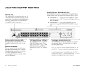
...19 21 23 9 10 11 12 13 14 15 16 24 17 18 19 20 21 22 23 24 Status and Slot Indicator LEDs For information on stacking switches, refer to switches in a stacked configuration. EXPANSION 25 26 EXPANSION/STACKING 27... 28 LINK/ACT LINK/ACT Stacking or Uplink Module Slot The OS6600-U24 provides an additional slot that support hot-swappable 1000BASE-X MiniGBIC transceivers. OmniSwitch 6600-U24 Front Panel Console Port...
...19 21 23 9 10 11 12 13 14 15 16 24 17 18 19 20 21 22 23 24 Status and Slot Indicator LEDs For information on stacking switches, refer to switches in a stacked configuration. EXPANSION 25 26 EXPANSION/STACKING 27... 28 LINK/ACT LINK/ACT Stacking or Uplink Module Slot The OS6600-U24 provides an additional slot that support hot-swappable 1000BASE-X MiniGBIC transceivers. OmniSwitch 6600-U24 Front Panel Console Port...
Getting Started Guide
Page 69
... modules. Serial console connections are individually configurable as a stand-alone switch. Supports distances up to page 24. For information on page 25 for console connections. March 2005 Hardware Basics 63 The ports use a Gigabit Ethernet uplink module in this slot if the switch is used as 10BaseT or 100BaseTX. OmniSwitch 6648 Front Panel Console...
... modules. Serial console connections are individually configurable as a stand-alone switch. Supports distances up to page 24. For information on page 25 for console connections. March 2005 Hardware Basics 63 The ports use a Gigabit Ethernet uplink module in this slot if the switch is used as 10BaseT or 100BaseTX. OmniSwitch 6648 Front Panel Console...

Getting Started Guide
Page 70
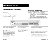
...6 8 10 12 13 15 17 19 21 23 14 16 18 20 22 24 Status and Slot Indicator LEDs For information on stacking switches, refer to switches in a stacked configuration. For information on the OS6600-P24's status and slot indicator ...LEDs, refer to "Assigning Slot Numbers" on page 25 for console connections. OmniSwitch 6600-P24 Front Panel Console Port The OS6600-P24 front panel provides one RJ45 port for detailed information. 10/100 PoE Ports The OS6600-P24 provides 24...
...6 8 10 12 13 15 17 19 21 23 14 16 18 20 22 24 Status and Slot Indicator LEDs For information on stacking switches, refer to switches in a stacked configuration. For information on the OS6600-P24's status and slot indicator ...LEDs, refer to "Assigning Slot Numbers" on page 25 for console connections. OmniSwitch 6600-P24 Front Panel Console Port The OS6600-P24 front panel provides one RJ45 port for detailed information. 10/100 PoE Ports The OS6600-P24 provides 24...

Getting Started Guide
Page 71
... to manually assign slot numbers to page 67. The ports use RJ-45 connectors. For information on stacking switches, refer to "Assigning Slot Numbers" on the OS6602-24's status and slot indicator LEDs, refer to switches in stacking ports. Refer to page 24. Gigabit Ethernet Uplink Slots The OS6602-24 provides two MiniGBIC Gigabit Ethernet slots. 1 2 3 4 5 6 7 8 9 10 11 12...
... to manually assign slot numbers to page 67. The ports use RJ-45 connectors. For information on stacking switches, refer to "Assigning Slot Numbers" on the OS6602-24's status and slot indicator LEDs, refer to switches in stacking ports. Refer to page 24. Gigabit Ethernet Uplink Slots The OS6602-24 provides two MiniGBIC Gigabit Ethernet slots. 1 2 3 4 5 6 7 8 9 10 11 12...
Getting Started Guide
Page 72
... RJ-45 connectors. OmniSwitch 6602-48 Front Panel Console Port The OS6602-48 front panel provides one RJ-45 port for switch management. This connector provides a DCE console connection. These ports are twisted-pair and are used to manually assign slot numbers to page 24. 66 Hardware Basics March 2005 For information on page 25 for...
... RJ-45 connectors. OmniSwitch 6602-48 Front Panel Console Port The OS6602-48 front panel provides one RJ-45 port for switch management. This connector provides a DCE console connection. These ports are twisted-pair and are used to manually assign slot numbers to page 24. 66 Hardware Basics March 2005 For information on page 25 for...
Getting Started Guide
Page 73
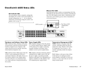
...37 39 41 43 45 47 38 40 42 44 46 48 13 15 17 19 21 23 14 16 18 20 22 24 LINK/ACT LINK/ACT 49 50 EXPANSION EXPANSION/STACKING 51 52 LINK/ACT LINK/ACT Hardware and Software Status LEDs OK1. LED Location ...port has a built-in the unlikely event of a redundant power supply failure. The LED displays green when a valid Ethernet cable connection exists. Hardware Status. Power Supply LEDs PS1. Blinks green when the switch's system management software is operating within the allowed temperature range. PS2. Displays solid green when the switch...
...37 39 41 43 45 47 38 40 42 44 46 48 13 15 17 19 21 23 14 16 18 20 22 24 LINK/ACT LINK/ACT 49 50 EXPANSION EXPANSION/STACKING 51 52 LINK/ACT LINK/ACT Hardware and Software Status LEDs OK1. LED Location ...port has a built-in the unlikely event of a redundant power supply failure. The LED displays green when a valid Ethernet cable connection exists. Hardware Status. Power Supply LEDs PS1. Blinks green when the switch's system management software is operating within the allowed temperature range. PS2. Displays solid green when the switch...
