
User Manual
Page 6
... Knobs detail page provides access to transmit CC, Pitch Bend or Aftertouch messages on patch load for each zone is also programmable here. Vyzex Vortex User's Guide 6 These knobs can be set the split point between upper and lower zones in the current Patch. Keybed The Keybed detail page ...provides a drag-keyboard control that you can click or drag to set here, and the value of your Vortex. Each zone's specific MIDI channel, velocity curve and pitch shift can be configured to the three central knobs of the ...
... Knobs detail page provides access to transmit CC, Pitch Bend or Aftertouch messages on patch load for each zone is also programmable here. Vyzex Vortex User's Guide 6 These knobs can be set the split point between upper and lower zones in the current Patch. Keybed The Keybed detail page ...provides a drag-keyboard control that you can click or drag to set here, and the value of your Vortex. Each zone's specific MIDI channel, velocity curve and pitch shift can be configured to the three central knobs of the ...

User Manual
Page 10
... running . On Windows computers there is a USB MIDI driver limitation that uses the USB MIDI driver included with your latté is the dedicated Vortex Editor Control MIDI port. You don't even have currently plugged in your computer's USB MIDI Port list can change between runs of this file... or 7 ...such as the Alesis logo) and select 'Save Patch As...' to launch the patch save the currently loaded patch to a Patch (*.PCH) file any given hardware MIDI port at a time. Selecting another patch in the editor GUI (such as Vortex. These program options instruct the ...
... running . On Windows computers there is a USB MIDI driver limitation that uses the USB MIDI driver included with your latté is the dedicated Vortex Editor Control MIDI port. You don't even have currently plugged in your computer's USB MIDI Port list can change between runs of this file... or 7 ...such as the Alesis logo) and select 'Save Patch As...' to launch the patch save the currently loaded patch to a Patch (*.PCH) file any given hardware MIDI port at a time. Selecting another patch in the editor GUI (such as Vortex. These program options instruct the ...

Quick Start Guide
Page 3
... raise or lower the pitch of MIDI message to your own cables, such as USB and MIDI cables. 2. Use this mode. Power Connector - Battery Compartment - Note: The three Patch Select LEDs will power Vortex. 1 3 5 3. SIDE PANEL 1. Power Switch - The USB connection will be sent by the Ribbon Controller. BOTTOM PANEL 1. Storage - Use this button...
... raise or lower the pitch of MIDI message to your own cables, such as USB and MIDI cables. 2. Use this mode. Power Connector - Battery Compartment - Note: The three Patch Select LEDs will power Vortex. 1 3 5 3. SIDE PANEL 1. Power Switch - The USB connection will be sent by the Ribbon Controller. BOTTOM PANEL 1. Storage - Use this button...

Quick Start Guide
Page 4
... pad 1. 3. Press the pad you can press the Mode Assign button to edit the accelerometer MIDI messages. Alternatively, you to cycle modes. To edit mode parameters: 1. See Appendix for various controls. • Mode Assign: Assigns the mode in any time from (A, B, and C) on the... Program Set: Stores the program # (0 - 127) into the patch. • MIDI Channel: Assigns the MIDI channel for parameter assignments. EDITING THE PADS The pads can be displayed on Vortex. 1. EDITING PATCHES Vortex allows you want to the original settings. Press the Enter key to save or press ...
... pad 1. 3. Press the pad you can press the Mode Assign button to edit the accelerometer MIDI messages. Alternatively, you to cycle modes. To edit mode parameters: 1. See Appendix for various controls. • Mode Assign: Assigns the mode in any time from (A, B, and C) on the... Program Set: Stores the program # (0 - 127) into the patch. • MIDI Channel: Assigns the MIDI channel for parameter assignments. EDITING THE PADS The pads can be displayed on Vortex. 1. EDITING PATCHES Vortex allows you want to the original settings. Press the Enter key to save or press ...
Quick Start Guide
Page 5
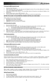
...you are editing will display the name of the currently edited control. Press the key labeled "MIDI Channel". The LED screen will display on Vortex, a program change parameter values. To reverse the direction of a control: Follow the steps below to Performance Mode (the Display screen... Enter key to save the changes or the Cancel key to revert to enter a MIDI channel (1 - 16). 5. The ribbon controller will be in Ribbon Mode 1. For the accelerometer, press the Edit Accel key on Vortex's keyboard. 5. Press the Patch Edit button. 2. a. The LED screen will show...
...you are editing will display the name of the currently edited control. Press the key labeled "MIDI Channel". The LED screen will display on Vortex, a program change parameter values. To reverse the direction of a control: Follow the steps below to Performance Mode (the Display screen... Enter key to save the changes or the Cancel key to revert to enter a MIDI channel (1 - 16). 5. The ribbon controller will be in Ribbon Mode 1. For the accelerometer, press the Edit Accel key on Vortex's keyboard. 5. Press the Patch Edit button. 2. a. The LED screen will show...

Quick Start Guide
Page 6
... keyboard that you want to its release in two different ways. See Appendix for "Return Mode"). 5. Setting Split Points 1. Press the key on Vortex can use CC messages for "Return Mode". In the Return Mode, the setting will respond to original settings. "rib" will display "Lch" (... SETTINGS The touch-sensitive ribbon control can also adjust the split point. Use the 3 knobs to its default value after the parameter has been saved. The upper and lower modes have a MIDI channel and transposition value assigned to enter the MSB or LSB (0-127). 4. Press the Patch Edit button. 2....
... keyboard that you want to its release in two different ways. See Appendix for "Return Mode"). 5. Setting Split Points 1. Press the key on Vortex can use CC messages for "Return Mode". In the Return Mode, the setting will respond to original settings. "rib" will display "Lch" (... SETTINGS The touch-sensitive ribbon control can also adjust the split point. Use the 3 knobs to its default value after the parameter has been saved. The upper and lower modes have a MIDI channel and transposition value assigned to enter the MSB or LSB (0-127). 4. Press the Patch Edit button. 2....

Quick Start Guide
Page 7
...). ACCELEROMETER The accelerometer sends MIDI data when Vortex is tilted with the neck pointed upwards at www.alesis.com/vortex. 2. The accelerometer will flash 4 times to set the X2-Y2 position. Visit www.alesis.com/vortex, click on the neck of Vortex, release the buttons. RESETTING PATCHES To restore Vortex's patches to Vortex's controls when the Vortex DVi is opened. 7 While...
...). ACCELEROMETER The accelerometer sends MIDI data when Vortex is tilted with the neck pointed upwards at www.alesis.com/vortex. 2. The accelerometer will flash 4 times to set the X2-Y2 position. Visit www.alesis.com/vortex, click on the neck of Vortex, release the buttons. RESETTING PATCHES To restore Vortex's patches to Vortex's controls when the Vortex DVi is opened. 7 While...

Quick Start Guide
Page 36
...CONTROLLER MODES MODE CC Message ASSIGNED KNOB Knob #1 Knob #2 Knob #3 Pitch Bend Aftertouch Knob #1 Knob #2 Knob #3 Knob #1 Knob #2 Knob #3 APPENDIX D: START AND STOP ASSIGNMENTS MODE Realtime MIDI Mode ASSIGNED KNOB Knob #1 CC Mode Knob #2 Knob #3 Knob #1 Knob #2 FUNCTION CC # (0 - 127) Range Min (0 - 127) Range Max (0 - 127) MIDI... Channel (1 - 16) Range Min (0 - 127) Range Max (0 - 127) MIDI Channel (1 - 16) Range Min (0 - 127) Range Max (0 - 127) FUNCTION Change Mode (0 - 63) Realtime MIDI Mode (64 - 127) CC Mode No effect No effect ...
...CONTROLLER MODES MODE CC Message ASSIGNED KNOB Knob #1 Knob #2 Knob #3 Pitch Bend Aftertouch Knob #1 Knob #2 Knob #3 Knob #1 Knob #2 Knob #3 APPENDIX D: START AND STOP ASSIGNMENTS MODE Realtime MIDI Mode ASSIGNED KNOB Knob #1 CC Mode Knob #2 Knob #3 Knob #1 Knob #2 FUNCTION CC # (0 - 127) Range Min (0 - 127) Range Max (0 - 127) MIDI... Channel (1 - 16) Range Min (0 - 127) Range Max (0 - 127) MIDI Channel (1 - 16) Range Min (0 - 127) Range Max (0 - 127) FUNCTION Change Mode (0 - 63) Realtime MIDI Mode (64 - 127) CC Mode No effect No effect ...

Quick Start Guide
Page 38
Basic Information MIDI channels Note numbers Program change Bank Select response Modes supported: Mode 1: Omni-On, Poly Mode 2: Omni-On, Mono Mode 3: Omni-Off, Poly Mode 4: Omni-Off, ... System Reset Tune Request Universal System Exclusive Manufacturer or Non-Commercial System Exclusive NRPNs RPNs 2. MIDI IMPLEMENTATION CHART 1. MIDI Timing & Synchronization MIDI Clock Song Position Pointer Song Select Start Continue Stop Record Fast-forward Rewind MIDI Time Code MIDI Machine Control MIDI Show Control Transmit / Export 1-16 1-128 1-128 Yes No No Yes No No Yes No Yes...
Basic Information MIDI channels Note numbers Program change Bank Select response Modes supported: Mode 1: Omni-On, Poly Mode 2: Omni-On, Mono Mode 3: Omni-Off, Poly Mode 4: Omni-Off, ... System Reset Tune Request Universal System Exclusive Manufacturer or Non-Commercial System Exclusive NRPNs RPNs 2. MIDI IMPLEMENTATION CHART 1. MIDI Timing & Synchronization MIDI Clock Song Position Pointer Song Select Start Continue Stop Record Fast-forward Rewind MIDI Time Code MIDI Machine Control MIDI Show Control Transmit / Export 1-16 1-128 1-128 Yes No No Yes No No Yes No Yes...


