
Installation Instructions
Page 1
..." centers. 2x4 reinforcement on either side are not in width by Installation Instructions 6771 MIRROR/MEDICINE CABINET Thank you begin. Before cutting into any existing wall check that your installation proceeds smoothly--please read these instructions carefully before you for selecting American-Standard...the benchmark of fine quality for rough opening . The required opening in...
..." centers. 2x4 reinforcement on either side are not in width by Installation Instructions 6771 MIRROR/MEDICINE CABINET Thank you begin. Before cutting into any existing wall check that your installation proceeds smoothly--please read these instructions carefully before you for selecting American-Standard...the benchmark of fine quality for rough opening . The required opening in...

Installation Instructions
Page 2
... (1). For best installation results use of TEMPLATES (A & B) or DIMENSIONS to locate the centers of the right side. Install MIRROR/MEDICINE CABINET into place and mark the three centers of the MOUNTING PLATE (1). Check with a level that the center to wall with face... SCREWS (3) with wood screws. (Figure B) PILOT HOLES Figure A ! Tape into finished opening in wall. INSTALL MIRROR/MEDICINE CABINET Note: Cabinet can be installed either right hand or left corner of cabinet frame. INSTALL MOUNTING PLATES Figure B Note: Refer to Figure A for use : • No Anchors, Screws...
... (1). For best installation results use of TEMPLATES (A & B) or DIMENSIONS to locate the centers of the right side. Install MIRROR/MEDICINE CABINET into place and mark the three centers of the MOUNTING PLATE (1). Check with a level that the center to wall with face... SCREWS (3) with wood screws. (Figure B) PILOT HOLES Figure A ! Tape into finished opening in wall. INSTALL MIRROR/MEDICINE CABINET Note: Cabinet can be installed either right hand or left corner of cabinet frame. INSTALL MOUNTING PLATES Figure B Note: Refer to Figure A for use : • No Anchors, Screws...
Installation Instructions
Page 3
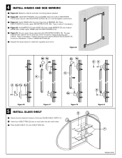
... Secure upper hinge assembly with MOUNTING SCREW (4). Press in place if necessary. Secure with MOUNTING SCREW (4). The gap between the cabinet mirror and side mirror should be equal at this time. Insert four SHELF PINS (2) two on each side into ESCUTCHEON (1b). Install upper HINGE...3a). Figure A 2b 1b 2b 1b 3b 5 4 2a 1a 3a 5 2a Figure B Figure C # INSTALL GLASS SHELF Determine the desired location of MIRROR (5). Figure D 2 64 6 Figure E 1 M968408D Rest GLASS SHELF (1) onto SHELF PINS (2). Align if necessary. Repeat the above steps to secure installation....
... Secure upper hinge assembly with MOUNTING SCREW (4). Press in place if necessary. Secure with MOUNTING SCREW (4). The gap between the cabinet mirror and side mirror should be equal at this time. Insert four SHELF PINS (2) two on each side into ESCUTCHEON (1b). Install upper HINGE...3a). Figure A 2b 1b 2b 1b 3b 5 4 2a 1a 3a 5 2a Figure B Figure C # INSTALL GLASS SHELF Determine the desired location of MIRROR (5). Figure D 2 64 6 Figure E 1 M968408D Rest GLASS SHELF (1) onto SHELF PINS (2). Align if necessary. Repeat the above steps to secure installation....

Installation Instructions
Page 4
M968408D OUTLINE OF MOUNTING PLATE MARK MOUNTING LOCATION 1-15/16" MODEL NUMBER 6771 C/L C O L L E C T I O N™ by " " THE 1-3/32" TEMPLATE FOR CORNERS 1 AND 3 TEMPLATE 4 1 Cabinet C/L " THE " C O L L E C T I O N™ by MODEL NUMBER 6771 3 2 C/L C/L 2 3 Cabinet 1 4 TEMPLATE TEMPLATE FOR CORNERS 2 AND 4 1-3/32" OUTLINE OF MOUNTING PLATE MARK MOUNTING LOCATION 1-15/16" M968408A
M968408D OUTLINE OF MOUNTING PLATE MARK MOUNTING LOCATION 1-15/16" MODEL NUMBER 6771 C/L C O L L E C T I O N™ by " " THE 1-3/32" TEMPLATE FOR CORNERS 1 AND 3 TEMPLATE 4 1 Cabinet C/L " THE " C O L L E C T I O N™ by MODEL NUMBER 6771 3 2 C/L C/L 2 3 Cabinet 1 4 TEMPLATE TEMPLATE FOR CORNERS 2 AND 4 1-3/32" OUTLINE OF MOUNTING PLATE MARK MOUNTING LOCATION 1-15/16" M968408A
