
Owners Manual
Page 20
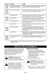
...26. Adjust gap if necessary. Check mower blade mounting hardware and all pivot points and pin connections. Replace worn or deteriorated belts. SERVICE AND ADJUSTMENTS Ariens Dealers will not tip over. Should engine service be required, it into service position. 5. Ensure unit is secure and ... then every 400 hours. See Hydraulic Fluid on page 28. CAUTION: HOT SURFACES may be obtained from operation. DO NOT touch engine or drive parts which may result in neutral and engage parking brake. 3. Place unit on a flat level surface. ALWAYS stop engine. Remove wing knob...
...26. Adjust gap if necessary. Check mower blade mounting hardware and all pivot points and pin connections. Replace worn or deteriorated belts. SERVICE AND ADJUSTMENTS Ariens Dealers will not tip over. Should engine service be required, it into service position. 5. Ensure unit is secure and ... then every 400 hours. See Hydraulic Fluid on page 28. CAUTION: HOT SURFACES may be obtained from operation. DO NOT touch engine or drive parts which may result in neutral and engage parking brake. 3. Place unit on a flat level surface. ALWAYS stop engine. Remove wing knob...

Owners Manual
Page 27
...on page 14). 2. Nuts Figure 17 PTO BELT WARNING: MOVING PARTS can cut or amputate body parts. Footboard in open position 2. Pivot Figure 18 Replacing Mower Belts NOTE: Long mower belt must be removed to the drive position when finished adjusting the brake. 1 ...CAUTION: DAMAGED OR WORN BELTS may result in most rearward position. 4. Adjust the Parking Brake 1....
...on page 14). 2. Nuts Figure 17 PTO BELT WARNING: MOVING PARTS can cut or amputate body parts. Footboard in open position 2. Pivot Figure 18 Replacing Mower Belts NOTE: Long mower belt must be removed to the drive position when finished adjusting the brake. 1 ...CAUTION: DAMAGED OR WORN BELTS may result in most rearward position. 4. Adjust the Parking Brake 1....
Owners Manual
Page 28
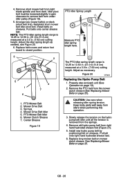
... blade spindle and from right hand hydrostat sheave first (Figure 21). 5. Put belts onto center sheave last. Adjust the idler spring length as necessary. Mower Drive Belt 3. PTO Mower Belt Idler 6. Springs 4. Slowly release the tension on page 27). 1. Arrange new mower belt(s) on page 27. NOTE: The PTO idler spring length range is 12...
... blade spindle and from right hand hydrostat sheave first (Figure 21). 5. Put belts onto center sheave last. Adjust the idler spring length as necessary. Mower Drive Belt 3. PTO Mower Belt Idler 6. Springs 4. Slowly release the tension on page 27). 1. Arrange new mower belt(s) on page 27. NOTE: The PTO idler spring length range is 12...

Parts Manual
Page 2
... 5 MAIN FRAME Frame 6 Seat 7 POWER PLANT Engine and Clutch 8 Fuel Tanks and Hoses 10 EPA Vent Lines 11 DRIVE TRAIN Hydro Drive 9 Transmission 12 Hydro-Gear Hydrostatic Pump 14 Wheels 18 Brakes and Linkage 20 HYDRAULICS Mechanical Lift 22 OPERATOR CONTROLS Steering Controls...Diagram 27 Electrical System 29 MOWER DECKS Deck, Discharge Chute, Anti-Scalp Rollers, & Belt Covers 30 Mounting Chains 32 Mounting Arms 33 Belts, Spindles, Idlers and Mower Blades - 52" & 60 34 Belts, Spindles, Idlers and Mower Blades - 48 36 3 © Copyright 2011 Ariens Company Safety 4 Decals -
... 5 MAIN FRAME Frame 6 Seat 7 POWER PLANT Engine and Clutch 8 Fuel Tanks and Hoses 10 EPA Vent Lines 11 DRIVE TRAIN Hydro Drive 9 Transmission 12 Hydro-Gear Hydrostatic Pump 14 Wheels 18 Brakes and Linkage 20 HYDRAULICS Mechanical Lift 22 OPERATOR CONTROLS Steering Controls...Diagram 27 Electrical System 29 MOWER DECKS Deck, Discharge Chute, Anti-Scalp Rollers, & Belt Covers 30 Mounting Chains 32 Mounting Arms 33 Belts, Spindles, Idlers and Mower Blades - 52" & 60 34 Belts, Spindles, Idlers and Mower Blades - 48 36 3 © Copyright 2011 Ariens Company Safety 4 Decals -

Parts Manual
Page 8
... x 2.00 Grade 5 15 06436200 1 Washer, Flat-Steel .406 x .812 x .065 16 07312500 1 Assembly, 4" Idler 17 00391900 1 Belt Finger 18 06436400 1 Washer, Flat, Steel .511 x 1.441 x .125 19 03796200 1 Assembly, Idler Pivot Arm (Includes item 4 and 7) 9 HYDRO DRIVE 17 3 12 3 Model 991085, 086, 087 13 14 15 16 1 2 7 3 4 5 6 9 11 8 10 18 19 Item...
... x 2.00 Grade 5 15 06436200 1 Washer, Flat-Steel .406 x .812 x .065 16 07312500 1 Assembly, 4" Idler 17 00391900 1 Belt Finger 18 06436400 1 Washer, Flat, Steel .511 x 1.441 x .125 19 03796200 1 Assembly, Idler Pivot Arm (Includes item 4 and 7) 9 HYDRO DRIVE 17 3 12 3 Model 991085, 086, 087 13 14 15 16 1 2 7 3 4 5 6 9 11 8 10 18 19 Item...

Operation Manual
Page 18
...of operation and then every 400 hours. WARNING: AVOID INJURY. Read and understand entire Safety section before servicing. DO NOT touch engine or drive parts which may result in neutral and engage parking brake. 3. ALWAYS stop engine. Sharpen or replace as required. Adjust gap if necessary... 6). GB - 18 Follow Engine Manual for dirt. Allow parts to keep your unit operating at peak efficiency. Replace worn or deteriorated belts. SERVICE AND ADJUSTMENTS Ariens Dealers will not tip over. Ensure unit is secure and will provide any service which are hot from...
...of operation and then every 400 hours. WARNING: AVOID INJURY. Read and understand entire Safety section before servicing. DO NOT touch engine or drive parts which may result in neutral and engage parking brake. 3. ALWAYS stop engine. Sharpen or replace as required. Adjust gap if necessary... 6). GB - 18 Follow Engine Manual for dirt. Allow parts to keep your unit operating at peak efficiency. Replace worn or deteriorated belts. SERVICE AND ADJUSTMENTS Ariens Dealers will not tip over. Ensure unit is secure and will provide any service which are hot from...

Operation Manual
Page 25
... Off on both sides of the unit (Figure 17). 1. Push the unit forward. Adjust the Parking Brake 1. Repeat as needed. 4. Check belts for moving parts to stop and park unit (See Operation on the parking brake cable adjuster and then turn the adjuster until all the tension...to the neutral position. Loosen the nuts on page 12). 2. NOTE: Set both transmission bypass valves to the drive position when finished adjusting the brake. 1 CAUTION: DAMAGED OR WORN BELTS may result in open position 2. If the unit easily rolls forward the transmission brakes are not fully engaging. ...
... Off on both sides of the unit (Figure 17). 1. Push the unit forward. Adjust the Parking Brake 1. Repeat as needed. 4. Check belts for moving parts to stop and park unit (See Operation on the parking brake cable adjuster and then turn the adjuster until all the tension...to the neutral position. Loosen the nuts on page 12). 2. NOTE: Set both transmission bypass valves to the drive position when finished adjusting the brake. 1 CAUTION: DAMAGED OR WORN BELTS may result in open position 2. If the unit easily rolls forward the transmission brakes are not fully engaging. ...
Operation Manual
Page 26
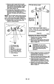
...length as necessary. Mower Drive Belt 3. Mower Clutch Sheave 7. Figure 20 OF4345 Replacing the Hydro Pump Belt 1. Put belt onto right hand hydrostat sheave last. 6. Center Sheave Figure 19 The PTO idler spring length range is 12.25 to 12.50 in. (31.0 to remove belt from the springs. 4....gain clearance to 31.8 cm) measured at a 3.0 in . (7.62 cm) cutting height. Replace belt covers and return foot board to 31.8 cm) measured at a 3.0 in . (7.62 cm) cutting height. Mower Drive Belt Idler 5. Slowly release the tension on page 25). GB - 26 NOTE: The PTO idler spring...
...length as necessary. Mower Drive Belt 3. Mower Clutch Sheave 7. Figure 20 OF4345 Replacing the Hydro Pump Belt 1. Put belt onto right hand hydrostat sheave last. 6. Center Sheave Figure 19 The PTO idler spring length range is 12.25 to 12.50 in. (31.0 to remove belt from the springs. 4....gain clearance to 31.8 cm) measured at a 3.0 in . (7.62 cm) cutting height. Replace belt covers and return foot board to 31.8 cm) measured at a 3.0 in . (7.62 cm) cutting height. Mower Drive Belt Idler 5. Slowly release the tension on page 25). GB - 26 NOTE: The PTO idler spring...


