

Owners Manual
Page 6
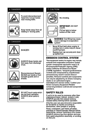
... or damage. Shut off engine, remove key, and read manual before operating unit. 3.1 Dismemberment Hazard To avoid dismemberment hazard do not put hands near moving belts. Keep hands away from all rotating or moving parts. DO NOT step or stand in operating position. Keep children and others away from unit while...
... or damage. Shut off engine, remove key, and read manual before operating unit. 3.1 Dismemberment Hazard To avoid dismemberment hazard do not put hands near moving belts. Keep hands away from all rotating or moving parts. DO NOT step or stand in operating position. Keep children and others away from unit while...
Owners Manual
Page 8
...mower. Environmental Protection Agency (EPA) and/or California Air Resources Board (CARB) regulations. Read, understand, and follow all rotating or moving belts. 7. 4. Keep hands away from operation. DANGER! DANGER! DO NOT touch parts which are hot from all safety practices in severe fines... or penalties. Only the user can only be used by an Ariens Company dealer or an authorized engine manufacturer's service center. WARNING: Overfilling may include exhaust and evaporative emissions control system components ...
...mower. Environmental Protection Agency (EPA) and/or California Air Resources Board (CARB) regulations. Read, understand, and follow all rotating or moving belts. 7. 4. Keep hands away from operation. DANGER! DANGER! DO NOT touch parts which are hot from all safety practices in severe fines... or penalties. Only the user can only be used by an Ariens Company dealer or an authorized engine manufacturer's service center. WARNING: Overfilling may include exhaust and evaporative emissions control system components ...

Owners Manual
Page 21
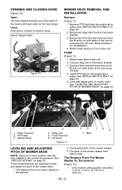
...and understand the entire Safety section before proceeding. TIPPING SEAT FORWARD (Figure 9) Move steering levers to zerk (1) on page 29 for hydrostatic belt location. Seat Tipped Forward 2. Steering Levers Figure 9 GB - 21 or Every Fasteners Replace fasteners that are missing or damaged. Tighten all... other fasteners. Season • Check PTO belt. Apply grease to the correct torque values. Work grease into mechanism by sliding seat back and forth repeatedly. 25 Hours or Every Season 1 2 50 Hours Check Check mower blade mounting hardware and all nuts and...
...and understand the entire Safety section before proceeding. TIPPING SEAT FORWARD (Figure 9) Move steering levers to zerk (1) on page 29 for hydrostatic belt location. Seat Tipped Forward 2. Steering Levers Figure 9 GB - 21 or Every Fasteners Replace fasteners that are missing or damaged. Tighten all... other fasteners. Season • Check PTO belt. Apply grease to the correct torque values. Work grease into mechanism by sliding seat back and forth repeatedly. 25 Hours or Every Season 1 2 50 Hours Check Check mower blade mounting hardware and all nuts and...
Owners Manual
Page 22
... page 35. Connect drag link to level and adjust the pitch of the unit using 3/8 nuts. 4. PTO Belt 3. Mower Deck 3 4. See "SPECIFICATIONS" on page 29. 2. The Distance From The Mower Blades To The Ground (Figure 12) • In the lowest cutting ... unit by removing the 3/8 nuts. Keep hardware for reinstallation. 4. Disconnect drag link from side-to close. Slide mower deck under unit. See "REPLACING PTO BELT" on the engine drive pulley. Level and adjust pitch of hood to -side. Three measurements are required to front deck bracket. 3. GB - 22 Remove ...
... page 35. Connect drag link to level and adjust the pitch of the unit using 3/8 nuts. 4. PTO Belt 3. Mower Deck 3 4. See "SPECIFICATIONS" on page 29. 2. The Distance From The Mower Blades To The Ground (Figure 12) • In the lowest cutting ... unit by removing the 3/8 nuts. Keep hardware for reinstallation. 4. Disconnect drag link from side-to close. Slide mower deck under unit. See "REPLACING PTO BELT" on the engine drive pulley. Level and adjust pitch of hood to -side. Three measurements are required to front deck bracket. 3. GB - 22 Remove ...

Owners Manual
Page 28
... NOTE: Reverse speed cannot be adjusted. Determine which way the unit turns. 2. Loosen jam nut on that is removed from PTO belt. 4. Remove belt covers from mower deck and engine drive pulley. If unit tracks excessively left when both steering levers are pushed as far forward as ... right or left or right in reverse, see your dealer for 30 feet (9.14 m). Figure 22 3. Lower Control Arm Figure 23 REPLACING PTO BELT Remove (Figure 24) 1. Adjust speed by: • Turning adjustment bolt clockwise to decrease steering lever travel. • Turning adjustment bolt counterclockwise...
... NOTE: Reverse speed cannot be adjusted. Determine which way the unit turns. 2. Loosen jam nut on that is removed from PTO belt. 4. Remove belt covers from mower deck and engine drive pulley. If unit tracks excessively left when both steering levers are pushed as far forward as ... right or left or right in reverse, see your dealer for 30 feet (9.14 m). Figure 22 3. Lower Control Arm Figure 23 REPLACING PTO BELT Remove (Figure 24) 1. Adjust speed by: • Turning adjustment bolt clockwise to decrease steering lever travel. • Turning adjustment bolt counterclockwise...

Owners Manual
Page 29
... 24 915159, 161, 171 4 1 2 1 3 Install (Figure 24) NOTE: Do not install PTO belt on mower deck. Rotate idler arm clockwise until idler pulley rests firmly against PTO belt. 4. NOTE: Ensure that belt is still positioned in step 1. 1. REPLACING HYDROSTATIC BELT Remove (Figure 26) 1. CAUTION: Use care when releasing idler spring tension. Deck Idler 4. Install...
... 24 915159, 161, 171 4 1 2 1 3 Install (Figure 24) NOTE: Do not install PTO belt on mower deck. Rotate idler arm clockwise until idler pulley rests firmly against PTO belt. 4. NOTE: Ensure that belt is still positioned in step 1. 1. REPLACING HYDROSTATIC BELT Remove (Figure 26) 1. CAUTION: Use care when releasing idler spring tension. Deck Idler 4. Install...

Owners Manual
Page 30
...Storage. IMPORTANT: NEVER store the engine with fuel in a clean dry area. Add Fuel Stabilizer 1. Re-start engine. 6. See "REPLACING PTO BELT" on idler, drive pulley, and hydrostatic transmission 2 pulleys. 2. Inspect unit for 1 to 2 minutes to be sure that treated gasoline has ...the engine outdoors for signs of a building with highpressure water or store unit outdoors. Turn engine OFF when it stops. Install PTO belt. Remove and fully charge battery. Slow the engine to avoid engine damage. 3. Long Term Storage Follow all fasteners are properly tightened. ...
...Storage. IMPORTANT: NEVER store the engine with fuel in a clean dry area. Add Fuel Stabilizer 1. Re-start engine. 6. See "REPLACING PTO BELT" on idler, drive pulley, and hydrostatic transmission 2 pulleys. 2. Inspect unit for 1 to 2 minutes to be sure that treated gasoline has ...the engine outdoors for signs of a building with highpressure water or store unit outdoors. Turn engine OFF when it stops. Install PTO belt. Remove and fully charge battery. Slow the engine to avoid engine damage. 3. Long Term Storage Follow all fasteners are properly tightened. ...

Owners Manual
Page 31
... plug wire(s) or replace spark plug(s). Contact your Ariens dealer. 1. Clean or replace air filter cartridge. Contact your Ariens dealer. 7. Refer to Engine Manual for detailed instructions. 2. Choke engaged. 2. Faulty hydrostatic belt. 3. Operator presence switch not depressed. 2. Tighten...or mower blades do not engage or shut off. Spark plug wire(s) loose or spark plug(s) faulty. 6. Replace hydrostatic belt. Contact your Ariens dealer. 1. Cooling system plugged. 3. Charge battery. PROBABLE CAUSE 1. Faulty engine. 1. Faulty engine. Refer to Engine...
... plug wire(s) or replace spark plug(s). Contact your Ariens dealer. 1. Clean or replace air filter cartridge. Contact your Ariens dealer. 7. Refer to Engine Manual for detailed instructions. 2. Choke engaged. 2. Faulty hydrostatic belt. 3. Operator presence switch not depressed. 2. Tighten...or mower blades do not engage or shut off. Spark plug wire(s) loose or spark plug(s) faulty. 6. Replace hydrostatic belt. Contact your Ariens dealer. 1. Cooling system plugged. 3. Charge battery. PROBABLE CAUSE 1. Faulty engine. 1. Faulty engine. Refer to Engine...

Owners Manual
Page 32
... replace mower blades (see REPLACING MOWER BLADE on page 23. 2. and 50-Inch Spindle Assembly 51520900 42-Inch Spindle Assembly 07100124 Front Wheel 07200116 34-Inch Deck Belt 07200010 HA Raw Laminated Belt Hydraulic Drive 03971900 34-Inch Mower Blade 03797300 34-Inch Mulching Blade 04265400 ...42-Inch Mower Blade 07200523 42-Inch Deck Belt 03971900 50-Inch Mower Blade 07200524 50-Inch Deck Belt ACCESSORIES See your authorized Ariens dealer to add ...
... replace mower blades (see REPLACING MOWER BLADE on page 23. 2. and 50-Inch Spindle Assembly 51520900 42-Inch Spindle Assembly 07100124 Front Wheel 07200116 34-Inch Deck Belt 07200010 HA Raw Laminated Belt Hydraulic Drive 03971900 34-Inch Mower Blade 03797300 34-Inch Mulching Blade 04265400 ...42-Inch Mower Blade 07200523 42-Inch Deck Belt 03971900 50-Inch Mower Blade 07200524 50-Inch Deck Belt ACCESSORIES See your authorized Ariens dealer to add ...
Owners Manual
Page 35
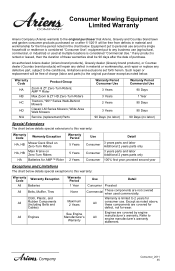
... warranty: Warranty Code Warranty Exception All Batteries All Belts, Muffler, Tires Cloth, Plastic, and All Rubber Components (Including Belts and Cables) All Engines Warranty Period Use Detail ...All consumer use (agricultural, commercial, or industrial) or used commercially. An authorized Ariens dealer (Ariens brand products), Gravely dealer (Gravely brand products), or Countax dealer (Countax brand ...of these components are covered by engine manufacturer's warranty. AMP™ Rider Max Zoom & ZT HD Zero-Turn Riders Tractors, "961" Series Walk-Behind Mowers Classic...
... warranty: Warranty Code Warranty Exception All Batteries All Belts, Muffler, Tires Cloth, Plastic, and All Rubber Components (Including Belts and Cables) All Engines Warranty Period Use Detail ...All consumer use (agricultural, commercial, or industrial) or used commercially. An authorized Ariens dealer (Ariens brand products), Gravely dealer (Gravely brand products), or Countax dealer (Countax brand ...of these components are covered by engine manufacturer's warranty. AMP™ Rider Max Zoom & ZT HD Zero-Turn Riders Tractors, "961" Series Walk-Behind Mowers Classic...
Parts Catalog
Page 3
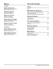
...Zoom 42) Kohler with 42" Mower Serial No. 010000 and up Model 915161 (Zoom 50) Kohler with 50" Mower Serial No. 010000 and up Model 915169 (Zoom 34 CARB) Briggs & Stratton with 34" Mower Serial No. 010000 and up Model 915171 (Zoom... 42 CARB) Kohler with 42" Mower Serial No. 010000 and up International Model 915322 (Zoom... Controls 20 FUEL TANKS AND ENGINE Engine, Exhaust, Belts and Idlers 22 Fuel Tank 24 ELECTRICAL SYSTEM Continuity ...
...Zoom 42) Kohler with 42" Mower Serial No. 010000 and up Model 915161 (Zoom 50) Kohler with 50" Mower Serial No. 010000 and up Model 915169 (Zoom 34 CARB) Briggs & Stratton with 34" Mower Serial No. 010000 and up Model 915171 (Zoom... 42 CARB) Kohler with 42" Mower Serial No. 010000 and up International Model 915322 (Zoom... Controls 20 FUEL TANKS AND ENGINE Engine, Exhaust, Belts and Idlers 22 Fuel Tank 24 ELECTRICAL SYSTEM Continuity ...

Parts Catalog
Page 22
ENGINE, EXHAUST, BELTS AND IDLERS Model 915157, 159, 161, 169, 171, 322, 323 35 34 39 8 37 6 31 28 Rear of Unit 33 38 1 6 36 3 1 34 35 8 15 7 5 4 32 18 2 2 14 22 12 19 18 21 16 23 30 20 25 29 24 17 28 27 13 18 26 9 10 11 22
ENGINE, EXHAUST, BELTS AND IDLERS Model 915157, 159, 161, 169, 171, 322, 323 35 34 39 8 37 6 31 28 Rear of Unit 33 38 1 6 36 3 1 34 35 8 15 7 5 4 32 18 2 2 14 22 12 19 18 21 16 23 30 20 25 29 24 17 28 27 13 18 26 9 10 11 22

Parts Catalog
Page 23
... .375-16 (915157, 169, 322) 1 Throttle/Choke Cable (915157, 169, 322) 1 Cable, Choke/Throttle Combo (915159, 161, 171, 323) 2 Screw, Tapping 10-24 x .50 Hex Washer Head 1 Oil Drain 4 Wire Clip (for .25" hole) 1 Muffler, Twin (915159, 161, 171, 323) 1 Muffler, B&S 208 BBZ (915157, 169) 1 Muffler, ...Spin Lock Flange .312-18 2 Nut, Locking Top Flange .31-18 1 Bracket, Clutch Stop 1 Bolt, Hex .31-18 x 2.75 1 Nut, Locking Nylon Flange .31-18 1 V-Belt, HA-RAW Edge Laminated 4 Washer, Locking .31 x .078 Regular (915159, 161, 171, 322, 323) 2 Washer, Locking .31 x .078 Regular (915157, 169) 4 Capscrew ....
... .375-16 (915157, 169, 322) 1 Throttle/Choke Cable (915157, 169, 322) 1 Cable, Choke/Throttle Combo (915159, 161, 171, 323) 2 Screw, Tapping 10-24 x .50 Hex Washer Head 1 Oil Drain 4 Wire Clip (for .25" hole) 1 Muffler, Twin (915159, 161, 171, 323) 1 Muffler, B&S 208 BBZ (915157, 169) 1 Muffler, ...Spin Lock Flange .312-18 2 Nut, Locking Top Flange .31-18 1 Bracket, Clutch Stop 1 Bolt, Hex .31-18 x 2.75 1 Nut, Locking Nylon Flange .31-18 1 V-Belt, HA-RAW Edge Laminated 4 Washer, Locking .31 x .078 Regular (915159, 161, 171, 322, 323) 2 Washer, Locking .31 x .078 Regular (915157, 169) 4 Capscrew ....
Parts Catalog
Page 33
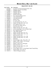
Qty. MOWER DECK, BELT AND IDLERS Model 915157, 169, 322 Item Part No. Description 1 51525400 1 Kit, Ariens 34" Deck wtih Decals (915157, 169) 04418859 1 2 61559900 2 3 04430867 1 4 07300039 2 5 03828859 1 6 06542000 5 7 03994300 1 8 00662659 1 9 01258100 1 10 06800002 1 11 06713500 1 12 06400006...-18 Plate, REINF, Spindle Washer, Flat Steel .469 x 2.00 x .25 Washer, Flat Steel .380 x 1.50 x .125 Bolt, Hex .38-16 x 3.00 Washer, Flat Steel .406 x 1.00 x .188 Washer, Flat Steel .438 x 1.00 x .083 Belt Finger Bushing, Flange, .625 x .750 x .500 x 1.00 Spacer, .375ID x .625D x 1.66 Promaster...
Qty. MOWER DECK, BELT AND IDLERS Model 915157, 169, 322 Item Part No. Description 1 51525400 1 Kit, Ariens 34" Deck wtih Decals (915157, 169) 04418859 1 2 61559900 2 3 04430867 1 4 07300039 2 5 03828859 1 6 06542000 5 7 03994300 1 8 00662659 1 9 01258100 1 10 06800002 1 11 06713500 1 12 06400006...-18 Plate, REINF, Spindle Washer, Flat Steel .469 x 2.00 x .25 Washer, Flat Steel .380 x 1.50 x .125 Bolt, Hex .38-16 x 3.00 Washer, Flat Steel .406 x 1.00 x .188 Washer, Flat Steel .438 x 1.00 x .083 Belt Finger Bushing, Flange, .625 x .750 x .500 x 1.00 Spacer, .375ID x .625D x 1.66 Promaster...

Parts Catalog
Page 35
...Kit, Ariens 50" Deck with Decals (915161) 04418959 1 Weldment, Deck 42" CE (915323) 2 51520900 3 Assembly, Spindle (915159, 171, 323) 51519500 3 Assembly, Spindle (915161) 3 03839059 3 Plate, Spindle 4 07415400 12 Screw, Tapping .38-16 x .75 Hex Washer Head 5 07300039 3 Assembly, Idler 4" 6 06400006 2 Washer, Flat Steel .406 x 1.50 x ...00 x .083 20 05961400 1 Bolt, Hex .38-16 x 2.75 21 04061059 1 Plate, Deck (915161) 22 07200523 1 V-Belt, 4L Wrapped (915159, 171, 323) 07200524 1 V-Belt, 4L Wrapped (915161) 23 04428900 1 Assy, Washout Port W/O Ring 24 07400103 2 Screw, Tapping .25-20 x .62 Hex ...
...Kit, Ariens 50" Deck with Decals (915161) 04418959 1 Weldment, Deck 42" CE (915323) 2 51520900 3 Assembly, Spindle (915159, 171, 323) 51519500 3 Assembly, Spindle (915161) 3 03839059 3 Plate, Spindle 4 07415400 12 Screw, Tapping .38-16 x .75 Hex Washer Head 5 07300039 3 Assembly, Idler 4" 6 06400006 2 Washer, Flat Steel .406 x 1.50 x ...00 x .083 20 05961400 1 Bolt, Hex .38-16 x 2.75 21 04061059 1 Plate, Deck (915161) 22 07200523 1 V-Belt, 4L Wrapped (915159, 171, 323) 07200524 1 V-Belt, 4L Wrapped (915161) 23 04428900 1 Assy, Washout Port W/O Ring 24 07400103 2 Screw, Tapping .25-20 x .62 Hex ...
Parts Catalog
Page 36
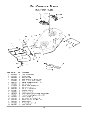
..., Hex .62-18 1 Bracket, Baffle Discharge 34" 2 Bolt, Hex .31-18 x .75 2 Nut, .31-18 Nyloc Flange 1 Wireform, Drag Link 2 Molded Cover, Belt 4 Screw, Tapping .25-20 x .50 Hex Washer Head 2 Pin, Bow Tie Locking Cotter .091 x 1.875 2 Screw, .31-18 x .75 2 Nut, Locking Top Flange .31-18 2 Washer, Flat Steel... .38 x .875 x .083 1 Spring, Torsion 1 Pin, Hair .08 x .18 x 1.18 1 Strap, Drag Link 36 10 19 13 4 BELT COVERS AND BLADES Model 915157, ...
..., Hex .62-18 1 Bracket, Baffle Discharge 34" 2 Bolt, Hex .31-18 x .75 2 Nut, .31-18 Nyloc Flange 1 Wireform, Drag Link 2 Molded Cover, Belt 4 Screw, Tapping .25-20 x .50 Hex Washer Head 2 Pin, Bow Tie Locking Cotter .091 x 1.875 2 Screw, .31-18 x .75 2 Nut, Locking Top Flange .31-18 2 Washer, Flat Steel... .38 x .875 x .083 1 Spring, Torsion 1 Pin, Hair .08 x .18 x 1.18 1 Strap, Drag Link 36 10 19 13 4 BELT COVERS AND BLADES Model 915157, ...

Parts Catalog
Page 38
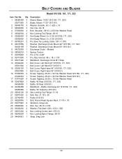
BELT COVERS AND BLADES Model 915159, 161, 171, 323 16 9 20 20 12 10 11 8 17 16 15 20 17 915159, 171, 323 14 5 6 4 7 29 13 21 2 1 21 24 3 20 18 19 23 9 15 17 16 17 14 20 12 22 25 26 20 20 26 27 915161 10 8 28 11 29 7 24 13 19 21 2 18 21 5 1 3 20 6 4 23 38
BELT COVERS AND BLADES Model 915159, 161, 171, 323 16 9 20 20 12 10 11 8 17 16 15 20 17 915159, 171, 323 14 5 6 4 7 29 13 21 2 1 21 24 3 20 18 19 23 9 15 17 16 17 14 20 12 22 25 26 20 20 26 27 915161 10 8 28 11 29 7 24 13 19 21 2 18 21 5 1 3 20 6 4 23 38
Parts Catalog
Page 39
..., Left Hand 42" (915159, 171, 323) 03901900 1 Belt Cover, Left Hand 50" (915161) 15 03902100 1 Belt Cover, Right Hand 42" (915159, 171, 323) 03901800 1 Belt Cover, Right Hand 50" (915161) 16 07400034 2 Screw, Tapping .25-20 x .50 Hex Washer Head (915159, 171, 323) 07400034 1 Screw, Tapping .25-20 x .50 Hex Washer Head (915161) 17 07414200 4 Screw, Tapping...
..., Left Hand 42" (915159, 171, 323) 03901900 1 Belt Cover, Left Hand 50" (915161) 15 03902100 1 Belt Cover, Right Hand 42" (915159, 171, 323) 03901800 1 Belt Cover, Right Hand 50" (915161) 16 07400034 2 Screw, Tapping .25-20 x .50 Hex Washer Head (915159, 171, 323) 07400034 1 Screw, Tapping .25-20 x .50 Hex Washer Head (915161) 17 07414200 4 Screw, Tapping...

Operation Manual
Page 17
... the entire Safety section before proceeding. Lubricate Apply grease to zerk (1) on page 23 for hydrostatic belt location). Season • Check PTO belt (see REPLACING PTO BELT on each Unit front wheel 25 Hours or Every Season 1 50 Hours Check Check mower blade mounting hardware and all nuts and Season bolts to desired position...
... the entire Safety section before proceeding. Lubricate Apply grease to zerk (1) on page 23 for hydrostatic belt location). Season • Check PTO belt (see REPLACING PTO BELT on each Unit front wheel 25 Hours or Every Season 1 50 Hours Check Check mower blade mounting hardware and all nuts and Season bolts to desired position...

Operation Manual
Page 18
...Drag Link 5. The distance from the front deck bracket. 3. The pitch of unit. 2. Ground Figure 8 GB - 18 Remove PTO belt from side-to the ground. 2. Front Trunnion 6. Lift Arms Figure 7 6 1 LEVELLING AND ADJUSTING PITCH OF MOWER DECK NOTE: ...bracket. 3. Mower Deck 2. Mower Blade 3. Slide mower deck under unit. Connect drag link to the correct air pressure (see REPLACING PTO BELT on page 23). PTO Belt 3. Install PTO belt on the engine drive pulley (see SPECIFICATIONS on page 18). 6 5 4 3 2 1. Mower Deck 4. Lowest Cutting Position 3 1 ...
...Drag Link 5. The distance from the front deck bracket. 3. The pitch of unit. 2. Ground Figure 8 GB - 18 Remove PTO belt from side-to the ground. 2. Front Trunnion 6. Lift Arms Figure 7 6 1 LEVELLING AND ADJUSTING PITCH OF MOWER DECK NOTE: ...bracket. 3. Mower Deck 2. Mower Blade 3. Slide mower deck under unit. Connect drag link to the correct air pressure (see REPLACING PTO BELT on page 23). PTO Belt 3. Install PTO belt on the engine drive pulley (see SPECIFICATIONS on page 18). 6 5 4 3 2 1. Mower Deck 4. Lowest Cutting Position 3 1 ...


