Owners Manual
Page 11
.... Stored energy in Operating Position (Figure 3) NOTE: The seat is an unusual vibration. Never store the machine or fuel container inside a building where there is desired tighten hardware. Clean grass and debris from unit, especially from container onto a level surface. Read and understand the entire Safety section before restarting. Unpack Unit...
.... Stored energy in Operating Position (Figure 3) NOTE: The seat is an unusual vibration. Never store the machine or fuel container inside a building where there is desired tighten hardware. Clean grass and debris from unit, especially from container onto a level surface. Read and understand the entire Safety section before restarting. Unpack Unit...
Owners Manual
Page 15
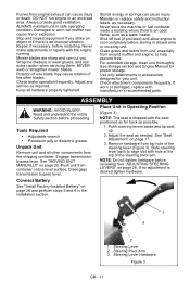
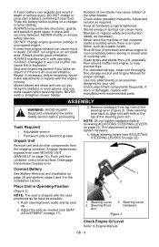
... engine 3 speed. Release mower lift pedal. 2 3 1 Steering Levers • Reverse (1) - Pull both steering levers to start a cold engine. Height of cut selector lever at the desired setting in the neutral position to neutral. Slow (3) - Pull right steering lever back or push left steering lever back or push right steering lever forward...
... engine 3 speed. Release mower lift pedal. 2 3 1 Steering Levers • Reverse (1) - Pull both steering levers to start a cold engine. Height of cut selector lever at the desired setting in the neutral position to neutral. Slow (3) - Pull right steering lever back or push left steering lever back or push right steering lever forward...
Owners Manual
Page 16
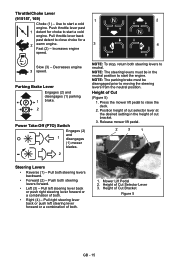
... Hose Coupling 3. Disengage the PTO switch, shut off water supply and repeat steps 4 through openings in place. Water can result in exposure to the desired position. Pull back the lock collar of the hose coupling and push the coupling onto the deck port until the coupling it tightly in the... the O-ring. Water supply should not pull more than 300 lbs. NOTE: If water leaks excessively from operation. GB - 16 Release lever to desired position. Tip the seat forward. Loosen mounting hardware and slide seat forward or backward to lock seat in a location where the dispersal of the mower...
... Hose Coupling 3. Disengage the PTO switch, shut off water supply and repeat steps 4 through openings in place. Water can result in exposure to the desired position. Pull back the lock collar of the hose coupling and push the coupling onto the deck port until the coupling it tightly in the... the O-ring. Water supply should not pull more than 300 lbs. NOTE: If water leaks excessively from operation. GB - 16 Release lever to desired position. Tip the seat forward. Loosen mounting hardware and slide seat forward or backward to lock seat in a location where the dispersal of the mower...

Owners Manual
Page 23
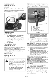
... 2. NOTE: This measurement must be taken when the mower blade ends point left and right. The distance from side to secure the link in the desired location. 4. NOTE: To avoid over-adjustment note which nuts have been adjusted and the amount each side of the mower deck. Mower Blade 3. GB - 23...
... 2. NOTE: This measurement must be taken when the mower blade ends point left and right. The distance from side to secure the link in the desired location. 4. NOTE: To avoid over-adjustment note which nuts have been adjusted and the amount each side of the mower deck. Mower Blade 3. GB - 23...

Owners Manual
Page 28
... the steering levers in reverse, see your dealer for 30 feet (9.14 m). Slowly release idler arm until tension is removed from the operator 2 position to desired position and tighten bolts. Lower Control Arm Figure 23 REPLACING PTO BELT Remove (Figure 24) 1. Rotate this end away from PTO belt. 4. Rotate steering lever...
... the steering levers in reverse, see your dealer for 30 feet (9.14 m). Slowly release idler arm until tension is removed from the operator 2 position to desired position and tighten bolts. Lower Control Arm Figure 23 REPLACING PTO BELT Remove (Figure 24) 1. Rotate this end away from PTO belt. 4. Rotate steering lever...
Operation Manual
Page 9
... remove safety devices. Adjust and service as possible. 1. Place Unit in safe operating condition. ALWAYS maintain unit in Operating Position (Figure 3) NOTE: The seat is desired tighten hardware. 4. Keep all other blades. NEVER weld or straighten mower blades. DO NOT charge or jump start a battery containing frozen fluid. A frozen battery can...
... remove safety devices. Adjust and service as possible. 1. Place Unit in safe operating condition. ALWAYS maintain unit in Operating Position (Figure 3) NOTE: The seat is desired tighten hardware. 4. Keep all other blades. NEVER weld or straighten mower blades. DO NOT charge or jump start a battery containing frozen fluid. A frozen battery can...

Operation Manual
Page 13
... fuel expansion. GASOLINE IMPORTANT: ALWAYS use a gasoline with up to evaporative emissions control system components. Press mower lift pedal and install adjustment pin in the desired adjustment hole. Mower Lift Pedal (Figure 5) Raises and lowers mower deck. Use a portable gasoline container with alcohols or ethers) can damage the fuel system or...
... fuel expansion. GASOLINE IMPORTANT: ALWAYS use a gasoline with up to evaporative emissions control system components. Press mower lift pedal and install adjustment pin in the desired adjustment hole. Mower Lift Pedal (Figure 5) Raises and lowers mower deck. Use a portable gasoline container with alcohols or ethers) can damage the fuel system or...

Operation Manual
Page 17
...SEAT ADJUSTMENT 1. Season • Check PTO belt (see REPLACING PTO BELT on each Unit front wheel 25 Hours or Every Season 1 50 Hours Check Check mower blade mounting hardware and all nuts and Season bolts to the correct torque values. Check All Replace worn or improperly... functioning PTO cables. Seat Tipped Forward 2. GB - 17 Lubricate Apply grease to desired position. Tighten all other fasteners. Read and understand the entire Safety section before proceeding. TIPPING SEAT FORWARD Put steering levers up and ...
...SEAT ADJUSTMENT 1. Season • Check PTO belt (see REPLACING PTO BELT on each Unit front wheel 25 Hours or Every Season 1 50 Hours Check Check mower blade mounting hardware and all nuts and Season bolts to the correct torque values. Check All Replace worn or improperly... functioning PTO cables. Seat Tipped Forward 2. GB - 17 Lubricate Apply grease to desired position. Tighten all other fasteners. Read and understand the entire Safety section before proceeding. TIPPING SEAT FORWARD Put steering levers up and ...

Operation Manual
Page 22
... steering lever travel. • Turning adjustment bolt counterclockwise to increase steering lever travel of the steering levers may need adjustment if the unit turns to desired position and tighten bolts. Tighten the jam nut. ADJUSTING STEERING LEVERS (Figure 15) Adjustment 3 Adjustment 1 1 3 Rotate this end away from the operator position to the...
... steering lever travel. • Turning adjustment bolt counterclockwise to increase steering lever travel of the steering levers may need adjustment if the unit turns to desired position and tighten bolts. Tighten the jam nut. ADJUSTING STEERING LEVERS (Figure 15) Adjustment 3 Adjustment 1 1 3 Rotate this end away from the operator position to the...