
AT3IONT-I Series user's manual
Page 3
Contents Notices...v Safety information vi About this guide vi AT3IONT-I Series specifications summary viii Chapter 1: Product introduction 1.1 Before you proceed 1-1 1.2 Motherboard overview 1-2 1.2.1 Motherboard layout 1-2 ... 1-11 1.8 Software support 1-16 1.8.1 Installing an operating system 1-16 1.8.2 Support DVD information 1-16 1.8.3 ASUS VideoSecurity 1-17 1.8.4 ASUS Home Theater Gate 1-19 Chapter 2: BIOS information 2.1 Managing and updating your BIOS 2-1 2.1.1 ASUS Update utility 2-1 2.1.2 ASUS EZ Flash 2 2-2 2.1.3 ASUS CrashFree BIOS 2-3 2.2 BIOS setup program 2-4 iii
Contents Notices...v Safety information vi About this guide vi AT3IONT-I Series specifications summary viii Chapter 1: Product introduction 1.1 Before you proceed 1-1 1.2 Motherboard overview 1-2 1.2.1 Motherboard layout 1-2 ... 1-11 1.8 Software support 1-16 1.8.1 Installing an operating system 1-16 1.8.2 Support DVD information 1-16 1.8.3 ASUS VideoSecurity 1-17 1.8.4 ASUS Home Theater Gate 1-19 Chapter 2: BIOS information 2.1 Managing and updating your BIOS 2-1 2.1.1 ASUS Update utility 2-1 2.1.2 ASUS EZ Flash 2 2-2 2.1.3 ASUS CrashFree BIOS 2-3 2.2 BIOS setup program 2-4 iii

AT3IONT-I Series user's manual
Page 6
... contact your power supply is broken, do not try to fix it supports. • Chapter 2: BIOS information This chapter tells how to change system settings through the BIOS Setup menus. Do not place the product in your retailer. Contact a qualified service technician or your ...About this guide is organized This guide contains the following parts: • Chapter 1: Product introduction This chapter describes the features of the BIOS parameters are also provided. vi These devices could interrupt the grounding circuit. • Ensure that your dealer immediately. • To avoid...
... contact your power supply is broken, do not try to fix it supports. • Chapter 2: BIOS information This chapter tells how to change system settings through the BIOS Setup menus. Do not place the product in your retailer. Contact a qualified service technician or your ...About this guide is organized This guide contains the following parts: • Chapter 1: Product introduction This chapter describes the features of the BIOS parameters are also provided. vi These devices could interrupt the grounding circuit. • Ensure that your dealer immediately. • To avoid...

AT3IONT-I Series user's manual
Page 8
... front panel to 1920 x 1536 x 32 Bpp @75Hz Supports HDMI with max. AT3IONT-I Series specifications summary CPU Chipset Front Side Bus Memory Graphics Expansion slot Storage Audio LAN USB ASUS special features Integrated Dual-Core Intel® Atom™ 330 processor NVIDIA® ION...modules * Refer to 10 USB 2.0/1.1 ports (4 ports at mid-board, 6 ports at back panel) ASUS CrashFree BIOS 3 ASUS EZ Flash 2 ASUS MyLogo 2™ ASUS AI NET 2 ASUS Express Gate Home Theater Gate ASUS Q-Fan Stack Cool3+ (continued on the next page) viii Integrated NVIDIA® ION™ graphics processor...
... front panel to 1920 x 1536 x 32 Bpp @75Hz Supports HDMI with max. AT3IONT-I Series specifications summary CPU Chipset Front Side Bus Memory Graphics Expansion slot Storage Audio LAN USB ASUS special features Integrated Dual-Core Intel® Atom™ 330 processor NVIDIA® ION...modules * Refer to 10 USB 2.0/1.1 ports (4 ports at mid-board, 6 ports at back panel) ASUS CrashFree BIOS 3 ASUS EZ Flash 2 ASUS MyLogo 2™ ASUS AI NET 2 ASUS Express Gate Home Theater Gate ASUS Q-Fan Stack Cool3+ (continued on the next page) viii Integrated NVIDIA® ION™ graphics processor...

AT3IONT-I Series user's manual
Page 9
... panel audio connector 1 x COM connector 1 x Chassis intrusion connector 1 x SATA power connector* 1 x 24-pin EATX power connector** * For AT3IONT-I DELUXE only ** For AT3IONT-I only 8 Mb Flash ROM, AMI BIOS, PnP, DMI2.0, WfM2.0, SMBIOS 2.5, ACPI v2.0a 2 x Serial ATA cables 1 x I/O shield 1 x User Manual 1 x SATA Power ...cable* 1 x Remote Controller* 1 x Receiver* 1 x WiFi antenna* 1 x 90W DC adapter* 1 x Power cord* * For AT3IONT-I DELUXE only Drivers ASUS PC Probe II ASUS ...
... panel audio connector 1 x COM connector 1 x Chassis intrusion connector 1 x SATA power connector* 1 x 24-pin EATX power connector** * For AT3IONT-I DELUXE only ** For AT3IONT-I only 8 Mb Flash ROM, AMI BIOS, PnP, DMI2.0, WfM2.0, SMBIOS 2.5, ACPI v2.0a 2 x Serial ATA cables 1 x I/O shield 1 x User Manual 1 x SATA Power ...cable* 1 x Remote Controller* 1 x Receiver* 1 x WiFi antenna* 1 x 90W DC adapter* 1 x Power cord* * For AT3IONT-I DELUXE only Drivers ASUS PC Probe II ASUS ...

AT3IONT-I Series user's manual
Page 11
... USB connector (10-1 pin USB78, USB910) Page 1-14 1-8 1-1 1-11 1-13 1-12 ASUS AT3IONT-I DELUXE Lithium Cell CMOS Power DDR3 DIMM_A1 (64bit, 240-pin module) BT_USB34 LAN1_USB12 RCA_OUT AUDIO ...BIOS 12 11 10 9 8 Place four screws into the chassis in this side towards the rear of the chassis. 1 2 3 4 17.1cm(6.75in) DC_PWR/ WiFi Antenna COM1 KB_USB56 SATA_PWR1 Super I/O 5 CPU_FAN Intel® HDMI VGA Place this user guide are for AT3IONT-I DELUXE only. 1.2 1.2.1 Motherboard overview Motherboard layout ASUS AT3IONT-I Series motherboards include AT3IONT-I and AT3IONT...
... USB connector (10-1 pin USB78, USB910) Page 1-14 1-8 1-1 1-11 1-13 1-12 ASUS AT3IONT-I DELUXE Lithium Cell CMOS Power DDR3 DIMM_A1 (64bit, 240-pin module) BT_USB34 LAN1_USB12 RCA_OUT AUDIO ...BIOS 12 11 10 9 8 Place four screws into the chassis in this side towards the rear of the chassis. 1 2 3 4 17.1cm(6.75in) DC_PWR/ WiFi Antenna COM1 KB_USB56 SATA_PWR1 Super I/O 5 CPU_FAN Intel® HDMI VGA Place this user guide are for AT3IONT-I DELUXE only. 1.2 1.2.1 Motherboard overview Motherboard layout ASUS AT3IONT-I Series motherboards include AT3IONT-I and AT3IONT...

AT3IONT-I Series user's manual
Page 16
... expansion cards. Secure the card to the card. 3. See Chapter 2 for later use . Keep the screw for information on the system and change the necessary BIOS settings, if any. Replace the system cover. 1.5.2 Configuring an expansion card After installing the expansion card, configure it supports. Unplug the power cord before adding... expansion cards. 1.5 Expansion slot In the future, you physical injury and damage motherboard components. 1.5.1 Installing an expansion card To install an expansion card: 1. Turn on BIOS setup. 2.
... expansion cards. Secure the card to the card. 3. See Chapter 2 for later use . Keep the screw for information on the system and change the necessary BIOS settings, if any. Replace the system cover. 1.5.2 Configuring an expansion card After installing the expansion card, configure it supports. Unplug the power cord before adding... expansion cards. 1.5 Expansion slot In the future, you physical injury and damage motherboard components. 1.5.1 Installing an expansion card To install an expansion card: 1. Turn on BIOS setup. 2.

AT3IONT-I Series user's manual
Page 17
... to pins 2-3. The onboard button cell battery powers the RAM data in CMOS. Hold down the key during the boot process and enter BIOS setup to clear the CMOS RTC RAM data. Keep the cap on CLRTC jumper default position. You can clear the CMOS memory of date... ON the computer. 4. After clearing the CMOS, reinstall the battery. 1.7 Connectors 1.7.1 Rear panel connectors 1 2 3 4 5 6 78 16 15 14 13 12 11 10 9 ASUS AT3IONT-I SERIES Clear RTC RAM To erase the RTC RAM: 1. Except when clearing the RTC RAM, never remove the cap on pins 2-3 for about 5-10 seconds...
... to pins 2-3. The onboard button cell battery powers the RAM data in CMOS. Hold down the key during the boot process and enter BIOS setup to clear the CMOS RTC RAM data. Keep the cap on CLRTC jumper default position. You can clear the CMOS memory of date... ON the computer. 4. After clearing the CMOS, reinstall the battery. 1.7 Connectors 1.7.1 Rear panel connectors 1 2 3 4 5 6 78 16 15 14 13 12 11 10 9 ASUS AT3IONT-I SERIES Clear RTC RAM To erase the RTC RAM: 1. Except when clearing the RTC RAM, never remove the cap on pins 2-3 for about 5-10 seconds...

AT3IONT-I Series user's manual
Page 20
... • For more details on a hard disk drive that includes a RAID/AHCI set the SATA Mode Select item in the BIOS to the RAID/AHCI Supplementary Guide included in the folder named Manual in the support DVD. 1-11 Chapter 1: Product introduction The ...GND RSATA_RXN1 RSATA_RXP1 GND RSATA_TXN1 RSATA_TXP1 GND GND RSATA_TXP3 RSATA_TXN3 GND RSATA_RXP3 RSATA_RXN3 GND AT3IONT-I DELUXE SATA2 GND RSATA_RXN2 RSATA_RXP2 GND RSATA_TXN2 RSATA_TXP2 GND SATA4 GND RSATA_TXP4 RSATA_TXN4 GND RSATA_RXP4 RSATA_RXN4 GND AT3IONT-I SERIES SATA connectors • Install the Windows® XP Service Pack ...
... • For more details on a hard disk drive that includes a RAID/AHCI set the SATA Mode Select item in the BIOS to the RAID/AHCI Supplementary Guide included in the folder named Manual in the support DVD. 1-11 Chapter 1: Product introduction The ...GND RSATA_RXN1 RSATA_RXP1 GND RSATA_TXN1 RSATA_TXP1 GND GND RSATA_TXP3 RSATA_TXN3 GND RSATA_RXP3 RSATA_RXN3 GND AT3IONT-I DELUXE SATA2 GND RSATA_RXN2 RSATA_RXP2 GND RSATA_TXN2 RSATA_TXP2 GND SATA4 GND RSATA_TXP4 RSATA_TXN4 GND RSATA_RXP4 RSATA_RXN4 GND AT3IONT-I SERIES SATA connectors • Install the Windows® XP Service Pack ...

AT3IONT-I Series user's manual
Page 22
... fan connectors! If you want to connect an AC'97 front panel audio module to this connector, set the Front Panel Select item in the BIOS setup to the fan connectors. 4. Do not place jumper caps on the motherboard, ensuring that supports either HD Audio or legacy AC`97 audio... standard. Do not forget to connect the fan cables to [HD Audio]. AT3IONT-I DELUXE GND PRESENCE# SENSE1_RETUR SENSE2_RETUR AGND NC NC NC AAFP PIN 1 PIN 1 MIC2 MICPWR Line out_R NC Line out_L PORT1 L PORT1 R PORT2 R SENSE_SEND ...
... fan connectors! If you want to connect an AC'97 front panel audio module to this connector, set the Front Panel Select item in the BIOS setup to the fan connectors. 4. Do not place jumper caps on the motherboard, ensuring that supports either HD Audio or legacy AC`97 audio... standard. Do not forget to connect the fan cables to [HD Audio]. AT3IONT-I DELUXE GND PRESENCE# SENSE1_RETUR SENSE2_RETUR AGND NC NC NC AAFP PIN 1 PIN 1 MIC2 MICPWR Line out_R NC Line out_L PORT1 L PORT1 R PORT2 R SENSE_SEND ...

AT3IONT-I Series user's manual
Page 31
... motherboard package. Quit all Windows® applications before you to restore the BIOS in the future. ASUS AT3IONT-I Series 2-1 Copy the original motherboard BIOS using this utility. Select the ASUS FTP site nearest you update the BIOS using the ASUS Update utility. 2.1.1 ASUS Update utility The ASUS Update is a utility that you need to avoid network traffic, or click...
... motherboard package. Quit all Windows® applications before you to restore the BIOS in the future. ASUS AT3IONT-I Series 2-1 Copy the original motherboard BIOS using this utility. Select the ASUS FTP site nearest you update the BIOS using the ASUS Update utility. 2.1.1 ASUS Update utility The ASUS Update is a utility that you need to avoid network traffic, or click...
AT3IONT-I Series user's manual
Page 32
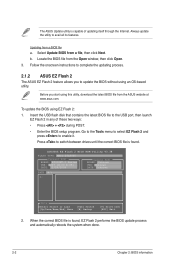
... is capable of these two ways: • Press + during POST. • Enter the BIOS setup program. Updating from the ASUS website at www.asus.com. ASUSTek EZ Flash 2 BIOS ROM Utility V3.38 FLASH TYPE: MXIC 25L8005 Current ROM BOARD: AT3IONT-I Series VER: 0207 (H:00 B:05) DATE: 12/29/2009 Update ROM BOARD: Unknown VER...
... is capable of these two ways: • Press + during POST. • Enter the BIOS setup program. Updating from the ASUS website at www.asus.com. ASUSTek EZ Flash 2 BIOS ROM Utility V3.38 FLASH TYPE: MXIC 25L8005 Current ROM BOARD: AT3IONT-I Series VER: 0207 (H:00 B:05) DATE: 12/29/2009 Update ROM BOARD: Unknown VER...

AT3IONT-I Series user's manual
Page 33
... The utility automatically checks the devices for details. When found, the utility reads the BIOS file and starts flashing the corrupted BIOS file. 4. Refer to the floppy disk drive, if supported. 3. ASUS AT3IONT-I Series 2-3 Insert the support DVD to the optical drive or the removable device that... allows you to ensure system compatibility and stability. Turn on again. Ensure to load the BIOS default settings to restore the BIOS file when it fails or gets...
... The utility automatically checks the devices for details. When found, the utility reads the BIOS file and starts flashing the corrupted BIOS file. 4. Refer to the floppy disk drive, if supported. 3. ASUS AT3IONT-I Series 2-3 Insert the support DVD to the optical drive or the removable device that... allows you to ensure system compatibility and stability. Turn on again. Ensure to load the BIOS default settings to restore the BIOS file when it fails or gets...

AT3IONT-I Series user's manual
Page 34
...its routines. If you failed to enter BIOS Setup using the BIOS Setup program. See section 2.8 Exit Menu. • The BIOS setup screens shown in using the first two options. Entering BIOS Setup at startup To enter BIOS Setup at www.asus.com to ensure optimum performance. Using the...Press the reset button on the system chassis. • Press the power button to your screen. • Visit the ASUS website at startup: • Press during the Power-On Self Test (POST). The BIOS screens include navigation keys and brief online help to select a field. Main Advanced Power...
...its routines. If you failed to enter BIOS Setup using the BIOS Setup program. See section 2.8 Exit Menu. • The BIOS setup screens shown in using the first two options. Entering BIOS Setup at startup To enter BIOS Setup at www.asus.com to ensure optimum performance. Using the...Press the reset button on the system chassis. • Press the power button to your screen. • Visit the ASUS website at startup: • Press during the Power-On Self Test (POST). The BIOS screens include navigation keys and brief online help to select a field. Main Advanced Power...

AT3IONT-I Series user's manual
Page 35
...the data transfer from and to set the system date. 2.3.3 SATA 1~4 While entering Setup, the BIOS automatically detects the presence of SATA devices. Configuration options: [Disabled] [Enabled] ASUS AT3IONT-I Series 2-5 Select ARMD (ATAPI Removable Media Device) if your device is a separate sub-menu ... to display the SATA device information. Configuration options: [Auto] [0] [1] [2] [3] [4] DMA Mode [Auto] Selects the DMA mode. The BIOS automatically detects the values opposite the dimmed items (Device, Vendor, Size, LBA Mode, Block Mode, PIO Mode, Async DMA, Ultra DMA, and...
...the data transfer from and to set the system date. 2.3.3 SATA 1~4 While entering Setup, the BIOS automatically detects the presence of SATA devices. Configuration options: [Disabled] [Enabled] ASUS AT3IONT-I Series 2-5 Select ARMD (ATAPI Removable Media Device) if your device is a separate sub-menu ... to display the SATA device information. Configuration options: [Auto] [0] [1] [2] [3] [4] DMA Mode [Auto] Selects the DMA mode. The BIOS automatically detects the values opposite the dimmed items (Device, Vendor, Size, LBA Mode, Block Mode, PIO Mode, Async DMA, Ultra DMA, and...

AT3IONT-I Series user's manual
Page 36
... Out (Sec) [5] Selects the time out value for detecting ATA/ATAPI devices. Allows you to set the OnChip SATA mode. The BIOS automatically detects the items in this menu allow you set the OnChip SATA Controller item to set or change the settings for the CPU and...: [0] [5] [10] [15] [20] [25] [30] [35] 2.3.5 System Information This menu gives you want to configure the item. BIOS Information Displays the auto-detected BIOS information. Processor Displays the auto-detected CPU specification. 2.3.4 Storage Configuration The items in this menu. Select an item then press if you an...
... Out (Sec) [5] Selects the time out value for detecting ATA/ATAPI devices. Allows you to set the OnChip SATA mode. The BIOS automatically detects the items in this menu allow you set the OnChip SATA Controller item to set or change the settings for the CPU and...: [0] [5] [10] [15] [20] [25] [30] [35] 2.3.5 System Information This menu gives you want to configure the item. BIOS Information Displays the auto-detected BIOS information. Processor Displays the auto-detected CPU specification. 2.3.4 Storage Configuration The items in this menu. Select an item then press if you an...

AT3IONT-I Series user's manual
Page 37
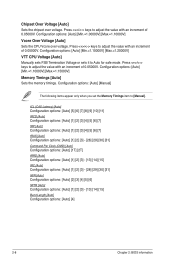
... clock mode. Configuration options: [Disabled] [Enabled] 2.4.2 JumperFree Configuration The items in this menu show the CPU-related information that the BIOS automatically detects. iGPU OverClock [450] Allows you to adjust the system frequency/voltage. Configuration options: [Min.=450] [Max.=999] Shader...set this item to Auto for safe mode. Set this item to zero (0). Configuration options: [Auto] [Min.=1.21000V] [Max.=2.47000V] ASUS AT3IONT-I Series 2-7 Press / keys to adjust the value with an increment of GPU overclocking options to achieve desired GPU frequency. 2.4.1 CPU ...
... clock mode. Configuration options: [Disabled] [Enabled] 2.4.2 JumperFree Configuration The items in this menu show the CPU-related information that the BIOS automatically detects. iGPU OverClock [450] Allows you to adjust the system frequency/voltage. Configuration options: [Min.=450] [Max.=999] Shader...set this item to Auto for safe mode. Set this item to zero (0). Configuration options: [Auto] [Min.=1.21000V] [Max.=2.47000V] ASUS AT3IONT-I Series 2-7 Press / keys to adjust the value with an increment of GPU overclocking options to achieve desired GPU frequency. 2.4.1 CPU ...
AT3IONT-I Series user's manual
Page 38
...: [Auto] [1] [2] [3] - [28] [29] [30] [31] tWR [Auto] Configuration options: [Auto] [2] [3] [4] [5] [6] tWTR [Auto] Configuration options: [Auto] [1] [2] [3] - [13] [14] [15] Burst Length [Auto] Configuration options: [Auto] [4] 2-8 Chapter 2: BIOS information Configuration options: [Auto] [Manual] The following items appear only when you set the Memory Timings item to Auto for safe mode. Configuration options: [Auto...
...: [Auto] [1] [2] [3] - [28] [29] [30] [31] tWR [Auto] Configuration options: [Auto] [2] [3] [4] [5] [6] tWTR [Auto] Configuration options: [Auto] [1] [2] [3] - [13] [14] [15] Burst Length [Auto] Configuration options: [Auto] [4] 2-8 Chapter 2: BIOS information Configuration options: [Auto] [Manual] The following items appear only when you set the Memory Timings item to Auto for safe mode. Configuration options: [Auto...
AT3IONT-I Series user's manual
Page 40
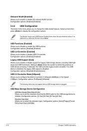
...to initialize. Configuration options: [Enabled] [Disabled] Legacy USB Support [Auto] Allows you to set the maximum time that the BIOS waits for Legacy USB storage devices, including USB flash drives and USB hard drives. If no USB device is disabled. If detected..., the USB controller legacy mode is plugged. Configuration options: [Auto] [Floppy] [Forced FDD] [Hard Disk] [CDROM] 2-10 Chapter 2: BIOS information Onboard WLAN [Enabled] Allows you to disable or enable the USB functions. Configuration options: [Enabled] [Disabled] 2.4.5 USB Configuration The items in ...
...to initialize. Configuration options: [Enabled] [Disabled] Legacy USB Support [Auto] Allows you to set the maximum time that the BIOS waits for Legacy USB storage devices, including USB flash drives and USB hard drives. If no USB device is disabled. If detected..., the USB controller legacy mode is plugged. Configuration options: [Auto] [Floppy] [Forced FDD] [Hard Disk] [CDROM] 2-10 Chapter 2: BIOS information Onboard WLAN [Enabled] Allows you to disable or enable the USB functions. Configuration options: [Enabled] [Disabled] 2.4.5 USB Configuration The items in ...

AT3IONT-I Series user's manual
Page 41
...In S1 sleep state, the system appears suspended and stays in the RSDT pointer list. When set to [No], BIOS configures all the devices in the Application-Specific Integrated Circuit (ASIC). Plug and Play O/S [No] When set to ...APM). When set to Enabled, the ACPI APIC table pointer is included in a low power mode. Main Advanced Power BIOS SETUP UTILITY Boot Tools Exit Suspend Mode ACPI 2.0 Support ACPI APIC Support Control EuP [Auto] [Disabled] [Enabled]... you to add more tables for legacy ISA devices. Configuration options: [Disabled] [Enabled] ASUS AT3IONT-I Series 2-11
...In S1 sleep state, the system appears suspended and stays in the RSDT pointer list. When set to [No], BIOS configures all the devices in the Application-Specific Integrated Circuit (ASIC). Plug and Play O/S [No] When set to ...APM). When set to Enabled, the ACPI APIC table pointer is included in a low power mode. Main Advanced Power BIOS SETUP UTILITY Boot Tools Exit Suspend Mode ACPI 2.0 Support ACPI APIC Support Control EuP [Auto] [Disabled] [Enabled]... you to add more tables for legacy ISA devices. Configuration options: [Disabled] [Enabled] ASUS AT3IONT-I Series 2-11

AT3IONT-I Series user's manual
Page 42
..., 3.3V Voltage, 5V Voltage, 12V Voltage [xxxV] or [Ignored] The onboard hardware monitor automatically detects the voltage output through the onboard voltage regulators. 2-12 Chapter 2: BIOS information Configuration options: [Disabled] [Enabled] Power On By PS/2 Keyboard [Disabled] Allows you do not wish to generate a wake event. Select Ignored if you to...
..., 3.3V Voltage, 5V Voltage, 12V Voltage [xxxV] or [Ignored] The onboard hardware monitor automatically detects the voltage output through the onboard voltage regulators. 2-12 Chapter 2: BIOS information Configuration options: [Disabled] [Enabled] Power On By PS/2 Keyboard [Disabled] Allows you do not wish to generate a wake event. Select Ignored if you to...


