
AT3IONT-I Series user's manual
Page 1
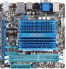
Motherboard AT3IONT-I DELUXE AT3IONT-I
Motherboard AT3IONT-I DELUXE AT3IONT-I

AT3IONT-I Series user's manual
Page 9
... 1 x Front panel audio connector 1 x COM connector 1 x Chassis intrusion connector 1 x SATA power connector* 1 x 24-pin EATX power connector** * For AT3IONT-I DELUXE only ** For AT3IONT-I only 8 Mb Flash ROM, AMI BIOS, PnP, DMI2.0, WfM2.0, SMBIOS 2.5, ACPI v2.0a 2 x Serial ATA cables 1 x I/O shield 1 x User ... Power cable* 1 x Remote Controller* 1 x Receiver* 1 x WiFi antenna* 1 x 90W DC adapter* 1 x Power cord* * For AT3IONT-I DELUXE only Drivers ASUS PC Probe II ASUS Update Anti-virus software (OEM version) Mini ITX form factor: 6.75 in x 6.75 in (17.1cm x 17.1cm) *Specifications are subject ...
... 1 x Front panel audio connector 1 x COM connector 1 x Chassis intrusion connector 1 x SATA power connector* 1 x 24-pin EATX power connector** * For AT3IONT-I DELUXE only ** For AT3IONT-I only 8 Mb Flash ROM, AMI BIOS, PnP, DMI2.0, WfM2.0, SMBIOS 2.5, ACPI v2.0a 2 x Serial ATA cables 1 x I/O shield 1 x User ... Power cable* 1 x Remote Controller* 1 x Receiver* 1 x WiFi antenna* 1 x 90W DC adapter* 1 x Power cord* * For AT3IONT-I DELUXE only Drivers ASUS PC Probe II ASUS Update Anti-virus software (OEM version) Mini ITX form factor: 6.75 in x 6.75 in (17.1cm x 17.1cm) *Specifications are subject ...

AT3IONT-I Series user's manual
Page 10
... on a grounded antistatic pad or in the bag that came with a standby power LED that lights up to page ix for buying an ASUS® AT3IONT-I SERIES Onboard LED 1-1 Chapter 1: Product introduction SB_PWR AT3IONT-I DELUXE ON OFF Standby Power Powered Off AT3IONT-I Series motherboard! Chapter 1 Product introduction Thank you for the list of accessories. •...
... on a grounded antistatic pad or in the bag that came with a standby power LED that lights up to page ix for buying an ASUS® AT3IONT-I SERIES Onboard LED 1-1 Chapter 1: Product introduction SB_PWR AT3IONT-I DELUXE ON OFF Standby Power Powered Off AT3IONT-I Series motherboard! Chapter 1 Product introduction Thank you for the list of accessories. •...

AT3IONT-I Series user's manual
Page 11
1.2 1.2.1 Motherboard overview Motherboard layout ASUS AT3IONT-I Series motherboards include AT3IONT-I and AT3IONT-I DELUXE two models The layout varies with external ports goes to the chassis. PWR_FAN Atom 330 CHA_FAN SPDIF_O 17.1cm(6.75in) DDR3 DIMM_A2 (64bit, 240-pin module) AT3IONT-I DELUXE Lithium Cell CMOS Power DDR3 DIMM_A1 (64bit, 240-pin module)..., SATA4) Front panel audio connector (10-1 pin AAFP) USB connector (10-1 pin USB78, USB910) Page 1-14 1-8 1-1 1-11 1-13 1-12 ASUS AT3IONT-I DELUXE only. The layout illustrations in the correct orientation. DDR3 DIMM slots 5.
1.2 1.2.1 Motherboard overview Motherboard layout ASUS AT3IONT-I Series motherboards include AT3IONT-I and AT3IONT-I DELUXE two models The layout varies with external ports goes to the chassis. PWR_FAN Atom 330 CHA_FAN SPDIF_O 17.1cm(6.75in) DDR3 DIMM_A2 (64bit, 240-pin module) AT3IONT-I DELUXE Lithium Cell CMOS Power DDR3 DIMM_A1 (64bit, 240-pin module)..., SATA4) Front panel audio connector (10-1 pin AAFP) USB connector (10-1 pin USB78, USB910) Page 1-14 1-8 1-1 1-11 1-13 1-12 ASUS AT3IONT-I DELUXE only. The layout illustrations in the correct orientation. DDR3 DIMM slots 5.

AT3IONT-I Series user's manual
Page 12
The figure illustrates the location of the DDR3 DIMM sockets: AT3IONT-I DELUXE DIMM_B1 DIMM_A1 Channel Channel A Channel B Sockets DIMM_A1 DIMM_B1 AT3IONT-I SERIES CPU 1.4 System memory 1.4.1 Overview The motherboard comes with an onboard Dual-Core Intel® Atom™ 330 processor and a specially designed CPU heatsink. AT3IONT-I DELUXE 1.3 Central Processing Unit (CPU) The motherboard comes with two Double Data Rate 3 (DDR3) Dual Inline Memory Modules (DIMM) sockets. Intel® Atom330 AT3IONT-I SERIES 240-pin DDR3 DIMM sockets 1-3 Chapter 1: Product introduction
The figure illustrates the location of the DDR3 DIMM sockets: AT3IONT-I DELUXE DIMM_B1 DIMM_A1 Channel Channel A Channel B Sockets DIMM_A1 DIMM_B1 AT3IONT-I SERIES CPU 1.4 System memory 1.4.1 Overview The motherboard comes with an onboard Dual-Core Intel® Atom™ 330 processor and a specially designed CPU heatsink. AT3IONT-I DELUXE 1.3 Central Processing Unit (CPU) The motherboard comes with two Double Data Rate 3 (DDR3) Dual Inline Memory Modules (DIMM) sockets. Intel® Atom330 AT3IONT-I SERIES 240-pin DDR3 DIMM sockets 1-3 Chapter 1: Product introduction

AT3IONT-I Series user's manual
Page 17
...pins 2-3. If the steps above do not help, remove the onboard battery and move the cap back to pins 1-2. 3. AT3IONT-I DELUXE 12 23 CLRTC Normal (Default) Clear RTC AT3IONT-I Series 1-8 Keep the cap on CLRTC jumper default position. Except when clearing the RTC RAM, never remove the cap .... After clearing the CMOS, reinstall the battery. 1.7 Connectors 1.7.1 Rear panel connectors 1 2 3 4 5 6 78 16 15 14 13 12 11 10 9 ASUS AT3IONT-I SERIES Clear RTC RAM To erase the RTC RAM: 1. Clear RTC RAM (3-pin CLRTC) This jumper allows you to clear the CMOS RTC RAM data...
...pins 2-3. If the steps above do not help, remove the onboard battery and move the cap back to pins 1-2. 3. AT3IONT-I DELUXE 12 23 CLRTC Normal (Default) Clear RTC AT3IONT-I Series 1-8 Keep the cap on CLRTC jumper default position. Except when clearing the RTC RAM, never remove the cap .... After clearing the CMOS, reinstall the battery. 1.7 Connectors 1.7.1 Rear panel connectors 1 2 3 4 5 6 78 16 15 14 13 12 11 10 9 ASUS AT3IONT-I SERIES Clear RTC RAM To erase the RTC RAM: 1. Clear RTC RAM (3-pin CLRTC) This jumper allows you to clear the CMOS RTC RAM data...

AT3IONT-I Series user's manual
Page 18
... (light blue). In the 4, 6, and 8-channel configurations, the function of this port becomes Front Speaker Out. 9. This port is for AT3IONT-I DELUXE only). Onboard Bluetooth module(for a PS/2 keyboard. 3. Intergrated 32-bit CPU with 32KB data RAM and 256KB program RAM; 5V single supply... to a Local Area Network (LAN) through a network hub. RCA Out port (right-channel) (for AT3IONT-I DELUXE only). Microphone port (pink). 1. PS/2 Keyboard port (purple). Open the Support DVD and click ASUS InstAll. 5. This port connects to the tape, CD, DVD player, or other VGA-compatible devices. ...
... (light blue). In the 4, 6, and 8-channel configurations, the function of this port becomes Front Speaker Out. 9. This port is for AT3IONT-I DELUXE only). Onboard Bluetooth module(for a PS/2 keyboard. 3. Intergrated 32-bit CPU with 32KB data RAM and 256KB program RAM; 5V single supply... to a Local Area Network (LAN) through a network hub. RCA Out port (right-channel) (for AT3IONT-I DELUXE only). Microphone port (pink). 1. PS/2 Keyboard port (purple). Open the Support DVD and click ASUS InstAll. 5. This port connects to the tape, CD, DVD player, or other VGA-compatible devices. ...

AT3IONT-I Series user's manual
Page 19
USB 2.0 ports 1 and 2. USB 2.0 ports 3 and 4. DC power port (for AT3IONT-I DELUXE only). RCA Out port (left-channel) (for AT3IONT-I DELUXE only). This port is for a High-Definition Multimedia Interface (HDMI) connector, and is HDCP compliant allowing playback of the audio ... devices. 13. Optical S/PDIF Out port. USB 2.0 ports 5 and 6. This port connects to an external audio output device via an RCA cable. 11. ASUS AT3IONT-I Series 1-10 These two 4-pin Universal Serial Bus (USB) ports are for USB 2.0 devices. 12. HDMI port. This port connects a receiver or a TV...
USB 2.0 ports 1 and 2. USB 2.0 ports 3 and 4. DC power port (for AT3IONT-I DELUXE only). RCA Out port (left-channel) (for AT3IONT-I DELUXE only). This port is for a High-Definition Multimedia Interface (HDMI) connector, and is HDCP compliant allowing playback of the audio ... devices. 13. Optical S/PDIF Out port. USB 2.0 ports 5 and 6. This port connects to an external audio output device via an RCA cable. 11. ASUS AT3IONT-I Series 1-10 These two 4-pin Universal Serial Bus (USB) ports are for USB 2.0 devices. 12. HDMI port. This port connects a receiver or a TV...

AT3IONT-I Series user's manual
Page 20
... connectors 1. SATA1 SATA3 GND RSATA_RXN1 RSATA_RXP1 GND RSATA_TXN1 RSATA_TXP1 GND GND RSATA_TXP3 RSATA_TXN3 GND RSATA_RXP3 RSATA_RXN3 GND AT3IONT-I DELUXE SATA2 GND RSATA_RXN2 RSATA_RXP2 GND RSATA_TXN2 RSATA_TXP2 GND SATA4 GND RSATA_TXP4 RSATA_TXN4 GND RSATA_RXP4 RSATA_RXN4 GND AT3IONT-I SERIES SATA connectors • Install the Windows® XP Service Pack 2 or later versions before using Serial...
... connectors 1. SATA1 SATA3 GND RSATA_RXN1 RSATA_RXP1 GND RSATA_TXN1 RSATA_TXP1 GND GND RSATA_TXP3 RSATA_TXN3 GND RSATA_RXP3 RSATA_RXN3 GND AT3IONT-I DELUXE SATA2 GND RSATA_RXN2 RSATA_RXP2 GND RSATA_TXN2 RSATA_TXP2 GND SATA4 GND RSATA_TXP4 RSATA_TXN4 GND RSATA_RXP4 RSATA_RXN4 GND AT3IONT-I SERIES SATA connectors • Install the Windows® XP Service Pack 2 or later versions before using Serial...

AT3IONT-I Series user's manual
Page 21
... the proper orientation and push down firmly until the connector completely fit. ASUS AT3IONT-I DELUXE only) This connector is for SATA power cable. SATA power connector (4-pin SATA_PWR1) (for USB 2.0 ports. AT3IONT-I DELUXE AT3IONT-I SERIES USB2.0 connectors Never connect a 1394 cable to a slot opening...separately. 2. Doing so will damage the motherboard! USB connectors (10-1 pin USB78, USB910) These connectors are for AT3IONT-I Series 1-12 AT3IONT-I DELUXE USB910 USB78 PIN 1 USB+5V USB_P9USB_P9+ GND USB+5V USB_P10USB_P10+ GND NC PIN 1 USB+5V USB_P7USB_P7+ GND USB+...
... the proper orientation and push down firmly until the connector completely fit. ASUS AT3IONT-I DELUXE only) This connector is for SATA power cable. SATA power connector (4-pin SATA_PWR1) (for USB 2.0 ports. AT3IONT-I DELUXE AT3IONT-I SERIES USB2.0 connectors Never connect a 1394 cable to a slot opening...separately. 2. Doing so will damage the motherboard! USB connectors (10-1 pin USB78, USB910) These connectors are for AT3IONT-I Series 1-12 AT3IONT-I DELUXE USB910 USB78 PIN 1 USB+5V USB_P9USB_P9+ GND USB+5V USB_P10USB_P10+ GND NC PIN 1 USB+5V USB_P7USB_P7+ GND USB+...

AT3IONT-I Series user's manual
Page 22
... is for details. 1-13 Chapter 1: Product introduction These are not jumpers! By default, this connector, set to [AC97]. 4. AT3IONT-I DELUXE GND PRESENCE# SENSE1_RETUR SENSE2_RETUR AGND NC NC NC AAFP PIN 1 PIN 1 MIC2 MICPWR Line out_R NC Line out_L PORT1 L PORT1 R PORT2... R SENSE_SEND PORT2 L AT3IONT-I DELUXE HD-audio-compliant Legacy AC'97 pin definition compliant definition AT3IONT-I /O module that you connect a high-definition front panel audio module to this connector to avail of the...
... is for details. 1-13 Chapter 1: Product introduction These are not jumpers! By default, this connector, set to [AC97]. 4. AT3IONT-I DELUXE GND PRESENCE# SENSE1_RETUR SENSE2_RETUR AGND NC NC NC AAFP PIN 1 PIN 1 MIC2 MICPWR Line out_R NC Line out_L PORT1 L PORT1 R PORT2... R SENSE_SEND PORT2 L AT3IONT-I DELUXE HD-audio-compliant Legacy AC'97 pin definition compliant definition AT3IONT-I /O module that you connect a high-definition front panel audio module to this connector to avail of the...

AT3IONT-I Series user's manual
Page 23
... 1-14 Connect the chassis power LED cable to this connector. The signal is removed or replaced. AT3IONT-I DELUXE CHASSIS GND Chassis Signal +5VSB_MB AT3IONT-I SERIES Chassis intrusion connector ASUS AT3IONT-I SERIES System panel connector • System power LED (2-pin PLED) This 2-pin connector is for the system power LED. System panel connector (10-1 pin F_PANEL...
... 1-14 Connect the chassis power LED cable to this connector. The signal is removed or replaced. AT3IONT-I DELUXE CHASSIS GND Chassis Signal +5VSB_MB AT3IONT-I SERIES Chassis intrusion connector ASUS AT3IONT-I SERIES System panel connector • System power LED (2-pin PLED) This 2-pin connector is for the system power LED. System panel connector (10-1 pin F_PANEL...

AT3IONT-I Series user's manual
Page 24
Serial port connectors (10-1 pin COM1) The connector is purchased separately. Connect the serial port module cable to the connector, then install the module to a slot opening at the back of the system chassis. COM1 PIN 1 AT3IONT-I SERIES Serial port (COM1) connector AT3IONT-I DELUXE 1-15 Chapter 1: Product introduction 8. The serial port bracket (COM1) is for a serial (COM) port.
Serial port connectors (10-1 pin COM1) The connector is purchased separately. Connect the serial port module cable to the connector, then install the module to a slot opening at the back of the system chassis. COM1 PIN 1 AT3IONT-I SERIES Serial port (COM1) connector AT3IONT-I DELUXE 1-15 Chapter 1: Product introduction 8. The serial port bracket (COM1) is for a serial (COM) port.

AT3IONT-I Series user's manual
Page 30
... Internet radio channel 1 to the USB 2.0 port 1 or 2 before using the remote controller. Actual behavior of the system sleep button. Using the remote controller (for AT3IONT-I DELUXE only) Use the remote controller to launch the ASUS Home Theater Gate and start media applications.
... Internet radio channel 1 to the USB 2.0 port 1 or 2 before using the remote controller. Actual behavior of the system sleep button. Using the remote controller (for AT3IONT-I DELUXE only) Use the remote controller to launch the ASUS Home Theater Gate and start media applications.

AT3IONT-I Series user's manual
Page 39
...VGA Card Exist] Allows you to select the Serial Port1 base address. Configuration options: [Disabled] [Enabled] The following two items appear only on AT3IONT-I Series 2-9 Configuration options: [Auto] [Disabled] Front Panel Select [HD Audio] Allows you to select the internal or external VGA card to ... controller. This item appears only when the Onboard LAN item is set HD Audio mode. Configuration options: [Enabled] [Disabled] ASUS AT3IONT-I DELUXE motherboard. Configuration options: [Enabled] [Disabled] LAN Option ROM [Disabled] Allows you to display the sub-menu.
...VGA Card Exist] Allows you to select the Serial Port1 base address. Configuration options: [Disabled] [Enabled] The following two items appear only on AT3IONT-I Series 2-9 Configuration options: [Auto] [Disabled] Front Panel Select [HD Audio] Allows you to select the internal or external VGA card to ... controller. This item appears only when the Onboard LAN item is set HD Audio mode. Configuration options: [Enabled] [Disabled] ASUS AT3IONT-I DELUXE motherboard. Configuration options: [Enabled] [Disabled] LAN Option ROM [Disabled] Allows you to display the sub-menu.

AT3IONT-I Series user's manual
Page 48
... Country: TAIWAN Authorized representative in Europe: ASUS COMPUTER GmbH Address, City: HARKORT STR. 21-23, 40880 RATINGEN Country: GERMANY declare the following apparatus: Product name : Motherboard Model name : AT3IONT-I DELUXE Conforms to begin affixing CE marking:2010 Signature... DECLARATION OF CONFORMITY Per FCC Part 2 Section 2. 1077(a) Responsible Party Name: Asus Computer International Address: 800 Corporate Way, Fremont, CA 94539...
... Country: TAIWAN Authorized representative in Europe: ASUS COMPUTER GmbH Address, City: HARKORT STR. 21-23, 40880 RATINGEN Country: GERMANY declare the following apparatus: Product name : Motherboard Model name : AT3IONT-I DELUXE Conforms to begin affixing CE marking:2010 Signature... DECLARATION OF CONFORMITY Per FCC Part 2 Section 2. 1077(a) Responsible Party Name: Asus Computer International Address: 800 Corporate Way, Fremont, CA 94539...


