User Guide
Page 13
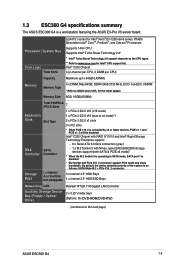
...Realtek® RTL8111H Gigabit LAN Controller 2 x 5.25" media bays (Options: No DVD-ROM/DVD-RW) (continued on the next page) ASUS ESC300 G4 1-3 Processor / System Bus Core Logic Total Slots LGA1151 socket for Intel® Xeon® E3-1200 v6/v5 series, 7th/6th Generation ...Boost Technology 2.0* * Intel® Turbo Boost Technology 2.0 support depends on the CPU types. ** Refer to ASUS server AVL for Intel® CPU support list. 1.3 ESC300 G4 specifications summary The ASUS ESC300 G4 is as follows: SATA Mode M.2 > PCIe X16_2 connector. Intel® C232 Chipset with RAID 0/1/5/10 ...
...Realtek® RTL8111H Gigabit LAN Controller 2 x 5.25" media bays (Options: No DVD-ROM/DVD-RW) (continued on the next page) ASUS ESC300 G4 1-3 Processor / System Bus Core Logic Total Slots LGA1151 socket for Intel® Xeon® E3-1200 v6/v5 series, 7th/6th Generation ...Boost Technology 2.0* * Intel® Turbo Boost Technology 2.0 support depends on the CPU types. ** Refer to ASUS server AVL for Intel® CPU support list. 1.3 ESC300 G4 specifications summary The ASUS ESC300 G4 is as follows: SATA Mode M.2 > PCIe X16_2 connector. Intel® C232 Chipset with RAID 0/1/5/10 ...
User Guide
Page 15
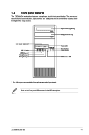
ASUS ESC300 G4 1-5 The power and reset buttons, LED indicators, optical drive, and USB ports are unavailable if the optional card reader is purchased. Refer to the Front ... button Power button HDD access LED * The USB 2.0 ports are all conveniently located at the front panel for the LED descriptions. 1.4 Front panel features The ESC300 G4 workstation features a simple yet stylish front panel design.
ASUS ESC300 G4 1-5 The power and reset buttons, LED indicators, optical drive, and USB ports are unavailable if the optional card reader is purchased. Refer to the Front ... button Power button HDD access LED * The USB 2.0 ports are all conveniently located at the front panel for the LED descriptions. 1.4 Front panel features The ESC300 G4 workstation features a simple yet stylish front panel design.
User Guide
Page 17
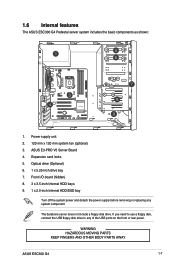
... the basic components as shown: 1. Optical drive (Optional) 6. 1 x 5.25-inch drive bay 7. WARNING HAZARDOUS MOVING PARTS KEEP FINGERS AND OTHER BODY PARTS AWAY ASUS ESC300 G4 1-7 Front I/O board (hidden) 8. 3 x 3.5-inch Internal HDD bays 9. 1 x 2.5-inch Internal HDD/SSD bay Turn off the system power and detach the ...power supply before removing or replacing any of the USB ports on the front or rear panel. ASUS E3-PRO V5 Server Board 4. Expansion card locks 5. The barebone server does not include a floppy disk drive. Power supply unit 2. ...
... the basic components as shown: 1. Optical drive (Optional) 6. 1 x 5.25-inch drive bay 7. WARNING HAZARDOUS MOVING PARTS KEEP FINGERS AND OTHER BODY PARTS AWAY ASUS ESC300 G4 1-7 Front I/O board (hidden) 8. 3 x 3.5-inch Internal HDD bays 9. 1 x 2.5-inch Internal HDD/SSD bay Turn off the system power and detach the ...power supply before removing or replacing any of the USB ports on the front or rear panel. ASUS E3-PRO V5 Server Board 4. Expansion card locks 5. The barebone server does not include a floppy disk drive. Power supply unit 2. ...
User Guide
Page 21
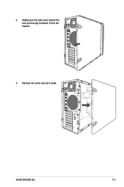
3. Slightly pull the side cover toward the rear just enough to detach it aside. Remove the cover and set it from the chassis. 4. ASUS ESC300 G4 2-3
3. Slightly pull the side cover toward the rear just enough to detach it aside. Remove the cover and set it from the chassis. 4. ASUS ESC300 G4 2-3
User Guide
Page 23
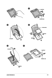
Load plate Load lever Retention tab Gold triangle mark Alignment key CPU notches Alignment key Load lever Retention lock ASUS ESC300 G4 Load lever Retention tab 2-5
Load plate Load lever Retention tab Gold triangle mark Alignment key CPU notches Alignment key Load lever Retention lock ASUS ESC300 G4 Load lever Retention tab 2-5
User Guide
Page 25
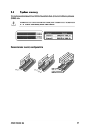
2.4 System memory The motherboard comes with four DDR 4 (Double Data Rate 4) Dual Inline Memory Modules (DIMM) slots. A DDR4 module is notched differently from a DDR, DDR2 or DDR3 module. DIMM_A1 DIMM_A2 DIMM_B1 DIMM_B2 Channel Channel A Channel B Sockets DIMM_A1 & DIMM_A2 DIMM_B1 & DIMM_B2 Recommended memory configurations ASUS ESC300 G4 2-7 DO NOT install a DDR, DDR2 or DDR3 memory module to the DDR4 slot.
2.4 System memory The motherboard comes with four DDR 4 (Double Data Rate 4) Dual Inline Memory Modules (DIMM) slots. A DDR4 module is notched differently from a DDR, DDR2 or DDR3 module. DIMM_A1 DIMM_A2 DIMM_B1 DIMM_B2 Channel Channel A Channel B Sockets DIMM_A1 & DIMM_A2 DIMM_B1 & DIMM_B2 Recommended memory configurations ASUS ESC300 G4 2-7 DO NOT install a DDR, DDR2 or DDR3 memory module to the DDR4 slot.
User Guide
Page 27
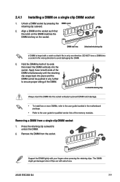
... DIMM notch damage. • To install two or more DIMMs, refer to the user guide bundled in only one direction. 2.4.1 Installing a DIMM on the socket. ASUS ESC300 G4 2-9
... DIMM notch damage. • To install two or more DIMMs, refer to the user guide bundled in only one direction. 2.4.1 Installing a DIMM on the socket. ASUS ESC300 G4 2-9
User Guide
Page 29
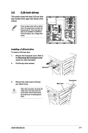
... To install a 5.25-inch drive: 1. Pull the bay locks outward. The lower bays (2 and 3) are available for more information. 2. Bay locks 3. Metal cover Screw driver ASUS ESC300 G4 2-11 Use tools such as a screw driver to bend and remove the metal cover to use. Take extra care when removing the metal cover.
... To install a 5.25-inch drive: 1. Pull the bay locks outward. The lower bays (2 and 3) are available for more information. 2. Bay locks 3. Metal cover Screw driver ASUS ESC300 G4 2-11 Use tools such as a screw driver to bend and remove the metal cover to use. Take extra care when removing the metal cover.
User Guide
Page 31
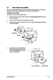
... (3) 3.5-inch Serial ATA hard disk drives via the hard disk drive bays and one 2.5-inch HDD/SSD drive at the bottom of the HDD cage. ASUS ESC300 G4 Screw hole (HDD cage) Screw holes (HDD) 2-13
... (3) 3.5-inch Serial ATA hard disk drives via the hard disk drive bays and one 2.5-inch HDD/SSD drive at the bottom of the HDD cage. ASUS ESC300 G4 Screw hole (HDD cage) Screw holes (HDD) 2-13
User Guide
Page 33
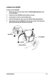
HDD cage lock HDD cage Matching screw holes 2.5-inch HDD/SSD ASUS ESC300 G4 2-15 Align and insert the 2.5-inch HDD/SSD into the drive bay as shown. Remove the side cover of screws. 3. Refer to the Removing the ...
HDD cage lock HDD cage Matching screw holes 2.5-inch HDD/SSD ASUS ESC300 G4 2-15 Align and insert the 2.5-inch HDD/SSD into the drive bay as shown. Remove the side cover of screws. 3. Refer to the Removing the ...
User Guide
Page 35
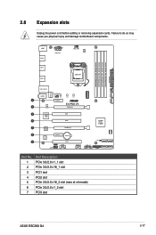
... No. 1 2 3 4 5 6 7 Slot Description PCIe 3.0/2.0 x1_1 slot PCIe 3.0/2.0 x16_1 slot PCI1 slot PCI2 slot PCIe 3.0/2.0 x16_2 slot (max at x4 mode) PCIe 3.0/2.0 x1_2 slot PCI3 slot ASUS ESC300 G4 2-17 2.8 Expansion slots Unplug the power cord before adding or removing expansion cards.
... No. 1 2 3 4 5 6 7 Slot Description PCIe 3.0/2.0 x1_1 slot PCIe 3.0/2.0 x16_1 slot PCI1 slot PCI2 slot PCIe 3.0/2.0 x16_2 slot (max at x4 mode) PCIe 3.0/2.0 x1_2 slot PCI3 slot ASUS ESC300 G4 2-17 2.8 Expansion slots Unplug the power cord before adding or removing expansion cards.
User Guide
Page 37
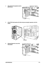
PCI-E latch ASUS ESC300 G4 2-19 Align and insert the expansion card into place securing the expansion card to the chassis. 6. (Optional) Replace the screw of the metal bracket. Lift the PCI-E latch inwards until it clicks into the PCI-E slot. Expansion card PCI-E slot 5. 4.
PCI-E latch ASUS ESC300 G4 2-19 Align and insert the expansion card into place securing the expansion card to the chassis. 6. (Optional) Replace the screw of the metal bracket. Lift the PCI-E latch inwards until it clicks into the PCI-E slot. Expansion card PCI-E slot 5. 4.

User Guide
Page 39
... the screw, the stand screw might be removed together with the screw you removed in step 2. Align and insert the M.2 card into the M.2 connector (M.2(SOCKET3)). 5. ASUS ESC300 G4 2-21 2.8.3 Installing M.2 (NGFF) cards To install an M.2 card: 1.
... the screw, the stand screw might be removed together with the screw you removed in step 2. Align and insert the M.2 card into the M.2 connector (M.2(SOCKET3)). 5. ASUS ESC300 G4 2-21 2.8.3 Installing M.2 (NGFF) cards To install an M.2 card: 1.
User Guide
Page 41
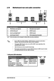
... steady) up from S5 mode Speed LED Status Description OFF 10Mbps connection ORANGE 100Mbps connection GREEN 1Gbps connection Activity Link Speed LED LED LAN port ASUS ESC300 G4 2-23 Line In port (light blue)** 7. PS/2 Mouse port (green) 5. LAN (RJ-45) port* 6. Line Out port (lime)** 8. 2.10 Motherboard rear and audio connection 1 2 34...
... steady) up from S5 mode Speed LED Status Description OFF 10Mbps connection ORANGE 100Mbps connection GREEN 1Gbps connection Activity Link Speed LED LED LAN port ASUS ESC300 G4 2-23 Line In port (light blue)** 7. PS/2 Mouse port (green) 5. LAN (RJ-45) port* 6. Line Out port (lime)** 8. 2.10 Motherboard rear and audio connection 1 2 34...

User Guide
Page 47
... SATA Mode Selection item in SATA mode, SATA port 1 will be disabled. • M.2 Socket and PCIe X16_2 connector support PCIe mode and share bandwidth. M.2(SOCKET3) ASUS ESC300 G4 3-5 M.2 socket 3 This socket allows you to [AHCI]. SATA6G GND RSATA_TXP RSATA_TXN GND RSATA_RXN RSATA_RXP GND 6. 4. Intel® C232 SATA 6.0Gb/s ports (7-pin SATA6G_1~6) These ports...
... SATA Mode Selection item in SATA mode, SATA port 1 will be disabled. • M.2 Socket and PCIe X16_2 connector support PCIe mode and share bandwidth. M.2(SOCKET3) ASUS ESC300 G4 3-5 M.2 socket 3 This socket allows you to [AHCI]. SATA6G GND RSATA_TXP RSATA_TXN GND RSATA_RXN RSATA_RXP GND 6. 4. Intel® C232 SATA 6.0Gb/s ports (7-pin SATA6G_1~6) These ports...
User Guide
Page 49
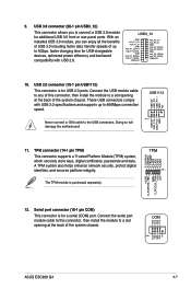
... 12. Serial port connector (10-1 pin COM) This connector is for additional USB 3.0 front or rear panel ports. COM PIN 1 DCD TXD GND RTS RI ASUS ESC300 G4 3-7 Doing so will damage the motherboard! USB+5V USB_P11USB_P11+ GND NC 9. USB 3.0 connector (20-1 pin USB3_12) This connector allows you can enjoy all the benefits...
... 12. Serial port connector (10-1 pin COM) This connector is for additional USB 3.0 front or rear panel ports. COM PIN 1 DCD TXD GND RTS RI ASUS ESC300 G4 3-7 Doing so will damage the motherboard! USB+5V USB_P11USB_P11+ GND NC 9. USB 3.0 connector (20-1 pin USB3_12) This connector allows you can enjoy all the benefits...

User Guide
Page 53
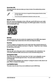
.... • If the system fails to boot after changing any BIOS setting, try to clear the CMOS and reset the motherboard to the default value. ASUS ESC300 G4 4-3 Entering BIOS at startup To enter BIOS Setup at startup, press during the Power-On Self Test (POST). Do this section are for information on...
.... • If the system fails to boot after changing any BIOS setting, try to clear the CMOS and reset the motherboard to the default value. ASUS ESC300 G4 4-3 Entering BIOS at startup To enter BIOS Setup at startup, press during the Power-On Self Test (POST). Do this section are for information on...

User Guide
Page 55
... configure the BIOS settings. To switch from EZ Mode to EZ Mode Search on the FAQ Displays the CPU temperature, CPU, and memory voltage output ASUS ESC300 G4 4-5 4.2.2 Advanced Mode The Advanced Mode provides advanced options for the detailed configurations.
... configure the BIOS settings. To switch from EZ Mode to EZ Mode Search on the FAQ Displays the CPU temperature, CPU, and memory voltage output ASUS ESC300 G4 4-5 4.2.2 Advanced Mode The Advanced Mode provides advanced options for the detailed configurations.
User Guide
Page 57
.... You can also scan the following keyboard functions: delete, cut, copy, and paste. • You can change the value of the field opposite the item. ASUS ESC300 G4 4-7 Quick Note (F9) This button above the menu bar allows you to key in notes of the activities that you have done in BIOS. •... the selected item. Use the navigation keys to enter your mobile device to connect to display the other items on the right side of the ASUS support website. Scroll bar A scroll bar appears on the screen. Press the Up/Down arrow keys or / keys to the BIOS FAQ web page of...
.... You can also scan the following keyboard functions: delete, cut, copy, and paste. • You can change the value of the field opposite the item. ASUS ESC300 G4 4-7 Quick Note (F9) This button above the menu bar allows you to key in notes of the activities that you have done in BIOS. •... the selected item. Use the navigation keys to enter your mobile device to connect to display the other items on the right side of the ASUS support website. Scroll bar A scroll bar appears on the screen. Press the Up/Down arrow keys or / keys to the BIOS FAQ web page of...
User Guide
Page 59
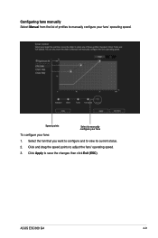
Click Apply to manually configure your fans To configure your fans' operating speed. Speed points Select to save the changes then click Exit (ESC). ASUS ESC300 G4 4-9 Click and drag the speed points to view its current status. 2. Select the fan that you want to configure and to adjust the fans' operating speed. 3. Configuring fans manually Select Manual from the list of profiles to manually configure your fans: 1.
Click Apply to manually configure your fans To configure your fans' operating speed. Speed points Select to save the changes then click Exit (ESC). ASUS ESC300 G4 4-9 Click and drag the speed points to view its current status. 2. Select the fan that you want to configure and to adjust the fans' operating speed. 3. Configuring fans manually Select Manual from the list of profiles to manually configure your fans: 1.


