
User Guide
Page 12
...RAMDisk ROG CPU-Z ROG MemTweakIt Kaspersky® Anti-Virus DAEMON Tools Pro Standard ASUS WebStorage Home Cloud ASUS Utilities ATX Form Factor, 12 in . (30.5 cm x 24.4 cm) Specifications are subject to change without notice. x 9.6 in . MAXIMUS VII HERO specifications summary Internal Connectors BIOS Features Manageability Software Form Factor 1 x USB 3.0 ...optional fan connector 4 x 4-pin Chassis fan connectors 1 x Thermal sensor connector (T-SENSOR1) 1 x 24-pin EATX power connector 1 x 8-pin EATX 12V Power connector 1 x Clear CMOS button 1 x Power-on button 1 x Reset button 1 x MemOK!
...RAMDisk ROG CPU-Z ROG MemTweakIt Kaspersky® Anti-Virus DAEMON Tools Pro Standard ASUS WebStorage Home Cloud ASUS Utilities ATX Form Factor, 12 in . (30.5 cm x 24.4 cm) Specifications are subject to change without notice. x 9.6 in . MAXIMUS VII HERO specifications summary Internal Connectors BIOS Features Manageability Software Form Factor 1 x USB 3.0 ...optional fan connector 4 x 4-pin Chassis fan connectors 1 x Thermal sensor connector (T-SENSOR1) 1 x 24-pin EATX power connector 1 x 8-pin EATX 12V Power connector 1 x Clear CMOS button 1 x Power-on button 1 x Reset button 1 x MemOK!

User Guide
Page 22
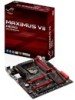
...PANEL) 15. ATX power connectors (24-pin EATXPWR; 8-pin EATX12V) 2. button 8. M.2 (Socket 3) 12. ROG Extension connector (18-1 pin ROG_EXT) 19. RESET button 9. Front panel audio connector (10-1 pin AAFP) Page 1-44 1-9 1-43 1-10 1-33 1-27 1-28 1-27 1-41 1-40 1-47 1-39 ...optional fan connectors (4-pin CPU_FAN; 4-pin CPU_OPT; 4-pin CHA_FAN1-4) 4. DDR3 DIMM slots 5. T_Sensor connector (2-pin T_SENSOR1) 16. LGA1150 CPU Socket 3. Clear CMOS button (CLR_CMOS) 20. Q_Code LEDs 6. ASMedia® Serial ATA 6 Gb/s connectors (7-pin SATA6G_E1/2 [red]) 14. START (Power-on) button 7. ...
...PANEL) 15. ATX power connectors (24-pin EATXPWR; 8-pin EATX12V) 2. button 8. M.2 (Socket 3) 12. ROG Extension connector (18-1 pin ROG_EXT) 19. RESET button 9. Front panel audio connector (10-1 pin AAFP) Page 1-44 1-9 1-43 1-10 1-33 1-27 1-28 1-27 1-41 1-40 1-47 1-39 ...optional fan connectors (4-pin CPU_FAN; 4-pin CPU_OPT; 4-pin CHA_FAN1-4) 4. DDR3 DIMM slots 5. T_Sensor connector (2-pin T_SENSOR1) 16. LGA1150 CPU Socket 3. Clear CMOS button (CLR_CMOS) 20. Q_Code LEDs 6. ASMedia® Serial ATA 6 Gb/s connectors (7-pin SATA6G_E1/2 [red]) 14. START (Power-on) button 7. ...

User Guide
Page 82
..., press during the Power-On Self Test (POST). Do this section are for more information on how to erase the RTC RAM via the Clear CMOS button. • The BIOS setup program does not support the bluetooth devices. See section Exit Menu for details. • If the system fails ...to boot after changing any BIOS setting, try to clear the CMOS and reset the motherboard to the default value. Entering BIOS Setup after POST To enter BIOS Setup after POST: • Press ++ simultaneously. • Press the...
..., press during the Power-On Self Test (POST). Do this section are for more information on how to erase the RTC RAM via the Clear CMOS button. • The BIOS setup program does not support the bluetooth devices. See section Exit Menu for details. • If the system fails ...to boot after changing any BIOS setting, try to clear the CMOS and reset the motherboard to the default value. Entering BIOS Setup after POST To enter BIOS Setup after POST: • Press ++ simultaneously. • Press the...

