
NCLV-D Series User Manual English Edition
Page 3
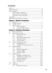
... find more information viii Conventions used in this guide ix Typography ix NCLV-D Series specifications summary x Chapter 1: Product introduction 1.1 Welcome 1-1 1.2 Package contents 1-1 1.3 Special features 1-2 1.3.1 Product highlights 1-2 1.3.2 Innovative ASUS features 1-4 Chapter 2: Hardware information 2.1 Before you proceed 2-1 2.2 Motherboard overview 2-2 2.2.1 Placement direction 2-2 2.2.2 Screw holes 2-2 2.2.3 CPU heatsink weight support 2-3 2.2.4 Motherboard layout 2-9 2.2.5 Layout contents 2-12 2.3 Central Processing Unit...
... find more information viii Conventions used in this guide ix Typography ix NCLV-D Series specifications summary x Chapter 1: Product introduction 1.1 Welcome 1-1 1.2 Package contents 1-1 1.3 Special features 1-2 1.3.1 Product highlights 1-2 1.3.2 Innovative ASUS features 1-4 Chapter 2: Hardware information 2.1 Before you proceed 2-1 2.2 Motherboard overview 2-2 2.2.1 Placement direction 2-2 2.2.2 Screw holes 2-2 2.2.3 CPU heatsink weight support 2-3 2.2.4 Motherboard layout 2-9 2.2.5 Layout contents 2-12 2.3 Central Processing Unit...
NCLV-D Series User Manual English Edition
Page 4
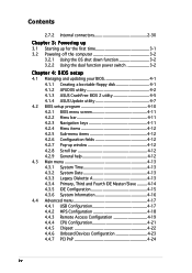
...function power switch 3-2 Chapter 4: BIOS setup 4.1 Managing and updating your BIOS 4-1 4.1.1 Creating a bootable floppy disk 4-1 4.1.2 AFUDOS utility 4-2 4.1.3 ASUS CrashFree BIOS 2 utility 4-5 4.1.4 ASUS Update utility 4-7 4.2 BIOS setup program 4-10 4.2.1 BIOS menu screen 4-11 4.2.2 Menu bar 4-11 4.2.3 Navigation keys 4-11 4.2.4 Menu items 4-12... 4.4 Advanced menu 4-17 4.4.1 USB Configuration 4-17 4.4.2 MPS Configuration 4-18 4.4.3 Remote Access Configuration 4-19 4.4.4 CPU Configuration 4-21 4.4.5 Chipset 4-22 4.4.6 Onboard Devices Configuration 4-23 4.4.7 PCI PnP 4-24 iv
...function power switch 3-2 Chapter 4: BIOS setup 4.1 Managing and updating your BIOS 4-1 4.1.1 Creating a bootable floppy disk 4-1 4.1.2 AFUDOS utility 4-2 4.1.3 ASUS CrashFree BIOS 2 utility 4-5 4.1.4 ASUS Update utility 4-7 4.2 BIOS setup program 4-10 4.2.1 BIOS menu screen 4-11 4.2.2 Menu bar 4-11 4.2.3 Navigation keys 4-11 4.2.4 Menu items 4-12... 4.4 Advanced menu 4-17 4.4.1 USB Configuration 4-17 4.4.2 MPS Configuration 4-18 4.4.3 Remote Access Configuration 4-19 4.4.4 CPU Configuration 4-21 4.4.5 Chipset 4-22 4.4.6 Onboard Devices Configuration 4-23 4.4.7 PCI PnP 4-24 iv

NCLV-D Series User Manual English Edition
Page 10
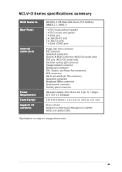
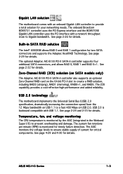
... Fan ASUS CrashFree BIOS 2 ASUS MyLogo2 (continued on the next page) x Zero-Channel RAID (optional) NCLV-DS model only Adaptec AIC-7901 PCI-X SCSI controller supports: - 1 x SCSI port with RAID 0, RAID 1, and RAID 0 +1 configuration - NCLV-D Series specifications summary CPU Chipset Front Side Bus Memory Expansion...) 1 x PCI-X 66 MHz/64-bit slot (PCI-X 1.0) 2 x PCI 33 MHz/32-bit/5V (PCI 2.3) 1 x Mini-PCI socket for the ASUS Server Management Board NCLV-DA/NCLV-DS supports: 1 x PCI-X 66 MHz/64-bit slot (supports ZCR, PCI-X 1.0) Intel® 6300ESB South Bridge supports: - 2 x Ultra DMA 100/...
... Fan ASUS CrashFree BIOS 2 ASUS MyLogo2 (continued on the next page) x Zero-Channel RAID (optional) NCLV-DS model only Adaptec AIC-7901 PCI-X SCSI controller supports: - 1 x SCSI port with RAID 0, RAID 1, and RAID 0 +1 configuration - NCLV-D Series specifications summary CPU Chipset Front Side Bus Memory Expansion...) 1 x PCI-X 66 MHz/64-bit slot (PCI-X 1.0) 2 x PCI 33 MHz/32-bit/5V (PCI 2.3) 1 x Mini-PCI socket for the ASUS Server Management Board NCLV-DA/NCLV-DS supports: 1 x PCI-X 66 MHz/64-bit slot (supports ZCR, PCI-X 1.0) Intel® 6300ESB South Bridge supports: - 2 x Ultra DMA 100/...
NCLV-D Series User Manual English Edition
Page 11
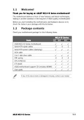
... (COM2) port Floppy disk drive connector IDE connector Serial ATA connectors Serial ATA RAID connectors (NCLV-DA model only) SCSI port (NCLV-DS model only) Hard disk activity LED connector Chassis intrusion connector Parallel port connector CPU, Chassis, and Power Fan connectors USB connectors SSI 24-pin and 8-pin PSU connector Serial ...power supply (with 24-pin and 8-pin 12 V plugs) ATX 12V 2.0 compliant E-ATX form factor: 12 in x 10.5 in (30.5 cm x 26.7 cm) Device drivers ASUS Server Web-based Management (ASWM) ASUS Live Update Utility *Specifications are subject to change without notice.
... (COM2) port Floppy disk drive connector IDE connector Serial ATA connectors Serial ATA RAID connectors (NCLV-DA model only) SCSI port (NCLV-DS model only) Hard disk activity LED connector Chassis intrusion connector Parallel port connector CPU, Chassis, and Power Fan connectors USB connectors SSI 24-pin and 8-pin PSU connector Serial ...power supply (with 24-pin and 8-pin 12 V plugs) ATX 12V 2.0 compliant E-ATX form factor: 12 in x 10.5 in (30.5 cm x 26.7 cm) Device drivers ASUS Server Web-based Management (ASWM) ASUS Live Update Utility *Specifications are subject to change without notice.
NCLV-D Series User Manual English Edition
Page 15
... technologies, making it , check the items in -1 disk drive cable CEK spring CPU X-PAD kit I/O shield ASUS motherboard support CD (includes ASWM) User guide NCLV-D Series -D -DA -DS 2 6 2 - - 2 2 2 If any of ASUS quality motherboards! Before you for the following items. Item ASUS NCLV-D Series motherboard Serial ATA signal cables Serial ATA power cables (dual-plug) SCSI...
... technologies, making it , check the items in -1 disk drive cable CEK spring CPU X-PAD kit I/O shield ASUS motherboard support CD (includes ASWM) User guide NCLV-D Series -D -DA -DS 2 6 2 - - 2 2 2 If any of ASUS quality motherboards! Before you for the following items. Item ASUS NCLV-D Series motherboard Serial ATA signal cables Serial ATA power cables (dual-plug) SCSI...
NCLV-D Series User Manual English Edition
Page 17
...32 for details. USB 2.0 is backward compatible with a network throughput close to Gigabit bandwidth. See page 2-24 and 2-35 for details. ASUS NCLV-D Series 1-3 Zero-Channel RAID (ZCR) solution (on SATA models only) The Adaptec AIC-8130 PCI-X SATA-II controller also supports an ... Adaptec HostRAID Technology. The ZCR capability provides a cost-effective high-performance and added reliability. Temperature, fan, and voltage monitoring The CPU temperature is monitored for timely failure detection. The ASIC monitors the voltage levels to provide a total solution for your networking needs....
...32 for details. USB 2.0 is backward compatible with a network throughput close to Gigabit bandwidth. See page 2-24 and 2-35 for details. ASUS NCLV-D Series 1-3 Zero-Channel RAID (ZCR) solution (on SATA models only) The Adaptec AIC-8130 PCI-X SATA-II controller also supports an ... Adaptec HostRAID Technology. The ZCR capability provides a cost-effective high-performance and added reliability. Temperature, fan, and voltage monitoring The CPU temperature is monitored for timely failure detection. The ASIC monitors the voltage levels to provide a total solution for your networking needs....
NCLV-D Series User Manual English Edition
Page 20
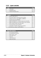
Chapter summary 2 2.1 Before you proceed 2-1 2.2 Motherboard overview 2-2 2.3 Central Processing Unit (CPU 2-14 2.4 System memory 2-18 2.5 Expansion slots 2-20 2.6 Jumpers 2-23 2.7 Connectors 2-29 ASUS NCLV-D Series
Chapter summary 2 2.1 Before you proceed 2-1 2.2 Motherboard overview 2-2 2.3 Central Processing Unit (CPU 2-14 2.4 System memory 2-18 2.5 Expansion slots 2-20 2.6 Jumpers 2-23 2.7 Connectors 2-29 ASUS NCLV-D Series
NCLV-D Series User Manual English Edition
Page 23
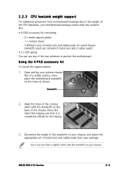
.... Open and lay your chassis. Press the sheet flat making sure that is completely affixed to the chassis. 3. ASUS NCLV-D Series 2-3 Standoff 2. 2.2.3 CPU heatsink weight support For additional protection from your motherboard package comes with the standoffs on your chassis, and select the ...weight of the chassis. Using the X-PAD accessory kit To install the support plates: 1. Determine the height of the standoffs on the base of the CPU heatsinks, your package. Align the holes of the contour sheet with two solution kits: • X-PAD accessory kit containing: - 2 x metal ...
.... Open and lay your chassis. Press the sheet flat making sure that is completely affixed to the chassis. 3. ASUS NCLV-D Series 2-3 Standoff 2. 2.2.3 CPU heatsink weight support For additional protection from your motherboard package comes with the standoffs on your chassis, and select the ...weight of the chassis. Using the X-PAD accessory kit To install the support plates: 1. Determine the height of the standoffs on the base of the CPU heatsinks, your package. Align the holes of the contour sheet with two solution kits: • X-PAD accessory kit containing: - 2 x metal ...
NCLV-D Series User Manual English Edition
Page 25
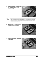
7. Repeat steps 4 and 7 to the metal nuts. 8. ASUS NCLV-D Series 2-5 Remove the contour sheet from the chassis. Make sure that the metal support plates fit perfectly to the rectangular cuts on the contour sheet. Carefully align and place the plate on a rectangular cut on the contour sheet; otherwise, the CPU heatsink screws would not align to prepare and install the second plate. 9.
7. Repeat steps 4 and 7 to the metal nuts. 8. ASUS NCLV-D Series 2-5 Remove the contour sheet from the chassis. Make sure that the metal support plates fit perfectly to the rectangular cuts on the contour sheet. Carefully align and place the plate on a rectangular cut on the contour sheet; otherwise, the CPU heatsink screws would not align to prepare and install the second plate. 9.
NCLV-D Series User Manual English Edition
Page 26
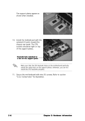
The CPU sockets should be right on the support plates; Secure the motherboard with the external I/O ports toward the chassis rear panel. otherwise, you can not install the CPU heatsinks properly. 11. The support plates appear as shown when installed. 10. Install the motherboard with nine (9) screws. Refer to a nut on the support plate Make sure that the CPU heatsink holes on the motherboard perfectly match the metal nuts on top of the support plates. Heatsink hole matched to section "2.2.2 Screw holes" for illustration. 2-6 Chapter 2: Hardware information
The CPU sockets should be right on the support plates; Secure the motherboard with the external I/O ports toward the chassis rear panel. otherwise, you can not install the CPU heatsinks properly. 11. The support plates appear as shown when installed. 10. Install the motherboard with nine (9) screws. Refer to a nut on the support plate Make sure that the CPU heatsink holes on the motherboard perfectly match the metal nuts on top of the support plates. Heatsink hole matched to section "2.2.2 Screw holes" for illustration. 2-6 Chapter 2: Hardware information
NCLV-D Series User Manual English Edition
Page 27
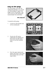
Locate the CPU heatsink holes on the motherboard. 2. Position the CEK spring underneath the motherboard, then match the CEK spring hooks to the upper CPU heatsink holes until they snap in place. ASUS NCLV-D Series 2-7 Press the upper spring hooks inward, then insert to the CPU1 heatsink holes. 3. Take note of the CPU heatsinks. You can also use these springs to support the weight of the four CEK spring hooks located beside the screw holes. CEK spring hook To install the CEK spring: 1. Using the CEK springs Two CEK springs come with the motherboard package.
Locate the CPU heatsink holes on the motherboard. 2. Position the CEK spring underneath the motherboard, then match the CEK spring hooks to the upper CPU heatsink holes until they snap in place. ASUS NCLV-D Series 2-7 Press the upper spring hooks inward, then insert to the CPU1 heatsink holes. 3. Take note of the CPU heatsinks. You can also use these springs to support the weight of the four CEK spring hooks located beside the screw holes. CEK spring hook To install the CEK spring: 1. Using the CEK springs Two CEK springs come with the motherboard package.
NCLV-D Series User Manual English Edition
Page 28
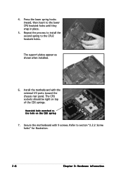
The CPU sockets should be right on the CEK spring 7. Refer to the hole on top of the CEK springs. Heatsink hole matched to section "2.2.2 Screw holes" for illustration. 2-8 Chapter 2: Hardware information Press the lower spring hooks inward, then insert to the CPU2 heatsink holes. The support plates appear as shown when installed. 6. Secure the motherboard with the external I/O ports toward the chassis rear panel. 4. Repeat the process to install the second spring to the lower CPU heatsink holes until they snap in place. 5. Install the motherboard with 9 screws.
The CPU sockets should be right on the CEK spring 7. Refer to the hole on top of the CEK springs. Heatsink hole matched to section "2.2.2 Screw holes" for illustration. 2-8 Chapter 2: Hardware information Press the lower spring hooks inward, then insert to the CPU2 heatsink holes. The support plates appear as shown when installed. 6. Secure the motherboard with the external I/O ports toward the chassis rear panel. 4. Repeat the process to install the second spring to the lower CPU heatsink holes until they snap in place. 5. Install the motherboard with 9 screws.
NCLV-D Series User Manual English Edition
Page 32
... FM_CPU1, FM_CPU2) 3. Gigabit LAN (BCM5721) controller setting (3-pin LAN_EN1) 6. VGA Graphics controller setting (3-pin VGA-EN1) 10. PS/2 mouse port (green) 2. LAN1 (RJ-45) port 7. CPU sockets 2. Gigabit LAN (BCM5705E) controller setting (3-pin LAN_EN2) 7. SATA controller setting (3-pin SATA_EN1) 8. 8130 LED setting (3-pin 8130LED1) 9. Video port 6. Keyboard power (3-pin KBPWR1) 5. 2.2.5 Layout...
... FM_CPU1, FM_CPU2) 3. Gigabit LAN (BCM5721) controller setting (3-pin LAN_EN1) 6. VGA Graphics controller setting (3-pin VGA-EN1) 10. PS/2 mouse port (green) 2. LAN1 (RJ-45) port 7. CPU sockets 2. Gigabit LAN (BCM5705E) controller setting (3-pin LAN_EN2) 7. SATA controller setting (3-pin SATA_EN1) 8. 8130 LED setting (3-pin 8130LED1) 9. Video port 6. Keyboard power (3-pin KBPWR1) 5. 2.2.5 Layout...
NCLV-D Series User Manual English Edition
Page 34
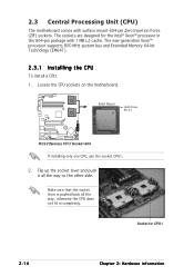
... CPU2 Gold Arrow Pin A1 NCLV(Series) CPU Socket 604 If installing only one CPU, use the socket CPU1. 2. 2.3 Central Processing Unit (CPU) The motherboard comes with 1 MB L2 cache. Flip up the socket lever and push it all the way, otherwise the CPU does not fit in the 604... The new generation Xeon™ processor supports 800 MHz system bus and Extended Memory 64-bit Technology (EM64T). 2.3.1 Installling the CPU To install a CPU: 1. The sockets are designed for CPU1 2-14 Chapter 2: Hardware information Socket for the Intel® Xeon™ processor in completely.
... CPU2 Gold Arrow Pin A1 NCLV(Series) CPU Socket 604 If installing only one CPU, use the socket CPU1. 2. 2.3 Central Processing Unit (CPU) The motherboard comes with 1 MB L2 cache. Flip up the socket lever and push it all the way, otherwise the CPU does not fit in the 604... The new generation Xeon™ processor supports 800 MHz system bus and Extended Memory 64-bit Technology (EM64T). 2.3.1 Installling the CPU To install a CPU: 1. The sockets are designed for CPU1 2-14 Chapter 2: Hardware information Socket for the Intel® Xeon™ processor in completely.
NCLV-D Series User Manual English Edition
Page 35
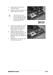
... grease) to prevent bending the pins and damaging the CPU! 5. DO NOT force the CPU into the socket until it is locked. 6. Marked corner (gold arrow) ASUS NCLV-D Series 2-15 3. The CPU fits only in place. Position the CPU above the socket as shown. 4. Carefully push down the... socket lever to install a second CPU. This thermal grease should come with the CPU package. 7. Repeat steps 1 to 6 if...
... grease) to prevent bending the pins and damaging the CPU! 5. DO NOT force the CPU into the socket until it is locked. 6. Marked corner (gold arrow) ASUS NCLV-D Series 2-15 3. The CPU fits only in place. Position the CPU above the socket as shown. 4. Carefully push down the... socket lever to install a second CPU. This thermal grease should come with the CPU package. 7. Repeat steps 1 to 6 if...
NCLV-D Series User Manual English Edition
Page 36
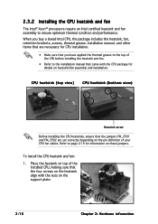
... the pin definition of your CPU fan cables. To install the CPU heatsink and fan: 1. CPU heatsink (top view) CPU heatsink (bottom view) Heatsink screw Before installing the CPU heatsinks, ensure that the four screws on the heatsink align with the CPU package for CPU installation. • Make sure... for details on these jumpers. Place the heatsink on top of the CPU before installing the heatsink and fan. • Refer to ensure optimum thermal condition and performance. When you buy a boxed Intel CPU, the package includes the heatsink, fan, retention brackets, screws, thermal ...
... the pin definition of your CPU fan cables. To install the CPU heatsink and fan: 1. CPU heatsink (top view) CPU heatsink (bottom view) Heatsink screw Before installing the CPU heatsinks, ensure that the four screws on the heatsink align with the CPU package for CPU installation. • Make sure... for details on these jumpers. Place the heatsink on top of the CPU before installing the heatsink and fan. • Refer to ensure optimum thermal condition and performance. When you buy a boxed Intel CPU, the package includes the heatsink, fan, retention brackets, screws, thermal ...
NCLV-D Series User Manual English Edition
Page 37
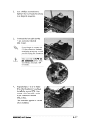
... 1 to 3 to install the other heatsink if you fail to connect the CPU fan connector! See page 2-24 for details. 4. Do not forget to plug this connector. ASUS NCLV-D Series 2-17 Hardware monitoring errors may occur if you have installed a second CPU, then connect the fan cable to the 4-pin connector labeled CPU_FAN1. Use...
... 1 to 3 to install the other heatsink if you fail to connect the CPU fan connector! See page 2-24 for details. 4. Do not forget to plug this connector. ASUS NCLV-D Series 2-17 Hardware monitoring errors may occur if you have installed a second CPU, then connect the fan cable to the 4-pin connector labeled CPU_FAN1. Use...

NCLV-D Series User Manual English Edition
Page 43
.... 6. The onboard button cell battery powers the RAM data in CMOS. Clear RTC RAM (CLRTC1) This jumper allows you to re-enter data. ASUS NCLV-D Series 2-23 Move the jumper cap from pins 1-2 (default) to pins 1-2. 4. For system failure due to overclocking. CLRTC1 21 32 Normal... NCLV(Series) Clear RTC RAM (Default) Clear CMOS You do not need to clear the RTC when the system hangs due to overclocking, use the C.P.R. (CPU Parameter Recall) feature. Shut down the key during the boot process and enter...
.... 6. The onboard button cell battery powers the RAM data in CMOS. Clear RTC RAM (CLRTC1) This jumper allows you to re-enter data. ASUS NCLV-D Series 2-23 Move the jumper cap from pins 1-2 (default) to pins 1-2. 4. For system failure due to overclocking. CLRTC1 21 32 Normal... NCLV(Series) Clear RTC RAM (Default) Clear CMOS You do not need to clear the RTC when the system hangs due to overclocking, use the C.P.R. (CPU Parameter Recall) feature. Shut down the key during the boot process and enter...
NCLV-D Series User Manual English Edition
Page 44
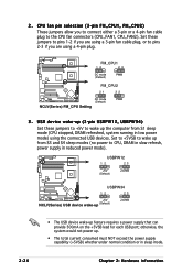
...FM_CPU2 21 32 DC mode (Default) NCLV(Series) FM_CPU Setting PWM 3 . otherwise, the system would not power up feature requires a power supply that can provide 500mA on the +5VSB lead for each USB port; Set to +5VSB to wake up from S1 sleep mode (CPU stopped, DRAM refreshed, system running ...in low power mode) using the connected USB devices. USBPW12 12 23 +5V (Default) +5VSB USBPW34 12 23 +5V NCLV(Series) USB device wake-up (Default) +5VSB • The USB device ...
...FM_CPU2 21 32 DC mode (Default) NCLV(Series) FM_CPU Setting PWM 3 . otherwise, the system would not power up feature requires a power supply that can provide 500mA on the +5VSB lead for each USB port; Set to +5VSB to wake up from S1 sleep mode (CPU stopped, DRAM refreshed, system running ...in low power mode) using the connected USB devices. USBPW12 12 23 +5V (Default) +5VSB USBPW34 12 23 +5V NCLV(Series) USB device wake-up (Default) +5VSB • The USB device ...

NCLV-D Series User Manual English Edition
Page 54
CPU and system fan connectors (4-pin CPU_FAN1/2, 3-pin REAR_FAN1/2, FRNT_FAN1/2) The fan connectors support cooling fans of 350 mA ~ 740 mA (8.88 W max.) or a total of ... GND +12V Rotation Rotation +12V GND CPU_FAN1 CPU_FAN2 GND FANPWR2 FANOUT4 GND FANPWR2 FANOUT4 FRNT_FAN1 FRNT_FAN2 NCLV(Series) Fan connectors FRNT_FAN1 FRNT_FAN2 Rotation +12V GND Rotation +12V GND 2-34 Chapter 2: Hardware information HDLED1 1 SCSI_ACTLED+ SCSI_ACTLEDSCSI_ACTLEDSCSI_ACTLED+ NCLV(Series) SCSI/SATA card activity LED connector 6 . Do not forget to connect the fan cables to...
CPU and system fan connectors (4-pin CPU_FAN1/2, 3-pin REAR_FAN1/2, FRNT_FAN1/2) The fan connectors support cooling fans of 350 mA ~ 740 mA (8.88 W max.) or a total of ... GND +12V Rotation Rotation +12V GND CPU_FAN1 CPU_FAN2 GND FANPWR2 FANOUT4 GND FANPWR2 FANOUT4 FRNT_FAN1 FRNT_FAN2 NCLV(Series) Fan connectors FRNT_FAN1 FRNT_FAN2 Rotation +12V GND Rotation +12V GND 2-34 Chapter 2: Hardware information HDLED1 1 SCSI_ACTLED+ SCSI_ACTLEDSCSI_ACTLEDSCSI_ACTLED+ NCLV(Series) SCSI/SATA card activity LED connector 6 . Do not forget to connect the fan cables to...


