
User Manual
Page 1
Motherboard
Motherboard

User Manual
Page 1
P5K SE/EPU Motherboard
P5K SE/EPU Motherboard
User Manual
Page 3
......vii Safety information viii About this guide ix P5K SE/EPU specifications summary xi Chapter 1: Product introduction 1.1 Welcome 1-1 1.2 Package contents 1-1 1.3 Special features 1-2 1.3.1 Product highlights 1-2 1.3.2 ASUS AI Lifestyle features 1-4 1.3.3 ASUS Stylish features 1-5 1.3.4 ASUS Intelligent Overclocking features 1-6 Chapter 2: Hardware information 2.1 Before you proceed 2-1 2.2 Motherboard overview 2-2 2.2.1 Placement direction 2-2 2.2.2 Screw holes 2-2 2.2.3 Motherboard layout 2-3 2.2.4 Layout contents 2-4 2.3 Central Processing Unit (CPU 2-6 2.3.1 Installing...
......vii Safety information viii About this guide ix P5K SE/EPU specifications summary xi Chapter 1: Product introduction 1.1 Welcome 1-1 1.2 Package contents 1-1 1.3 Special features 1-2 1.3.1 Product highlights 1-2 1.3.2 ASUS AI Lifestyle features 1-4 1.3.3 ASUS Stylish features 1-5 1.3.4 ASUS Intelligent Overclocking features 1-6 Chapter 2: Hardware information 2.1 Before you proceed 2-1 2.2 Motherboard overview 2-2 2.2.1 Placement direction 2-2 2.2.2 Screw holes 2-2 2.2.3 Motherboard layout 2-3 2.2.4 Layout contents 2-4 2.3 Central Processing Unit (CPU 2-6 2.3.1 Installing...
User Manual
Page 8
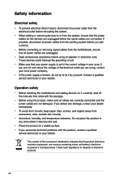
...If you detect any area where it by yourself. Do not place the product in municipal waste. Operation safety • Before installing the motherboard and adding devices on a stable surface. • If you encounter technical problems with the package. • Before using the product,... qualified service technician or your dealer immediately. • To avoid short circuits, keep paper clips, screws, and staples away from the motherboard, ensure that all power cables from the existing system before the signal cables are connected. Safety information Electrical safety • To prevent ...
...If you detect any area where it by yourself. Do not place the product in municipal waste. Operation safety • Before installing the motherboard and adding devices on a stable surface. • If you encounter technical problems with the package. • Before using the product,... qualified service technician or your dealer immediately. • To avoid short circuits, keep paper clips, screws, and staples away from the motherboard, ensure that all power cables from the existing system before the signal cables are connected. Safety information Electrical safety • To prevent ...
User Manual
Page 9
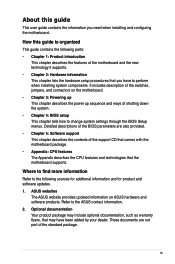
... Chapter 4: BIOS setup This chapter tells how to the ASUS contact information. 2. Where to find more information Refer to perform when installing system components. ASUS websites The ASUS website provides updated information on the motherboard. • Chapter 3: Powering up This chapter describes the... power up sequence and ways of the support CD that comes with the motherboard package. • Appendix: ...
... Chapter 4: BIOS setup This chapter tells how to the ASUS contact information. 2. Where to find more information Refer to perform when installing system components. ASUS websites The ASUS website provides updated information on the motherboard. • Chapter 3: Powering up This chapter describes the... power up sequence and ways of the support CD that comes with the motherboard package. • Appendix: ...

User Manual
Page 13
This chapter describes the motherboard features and the new technologies it supports. Chapter 1: 1Product introduction
This chapter describes the motherboard features and the new technologies it supports. Chapter 1: 1Product introduction
User Manual
Page 15
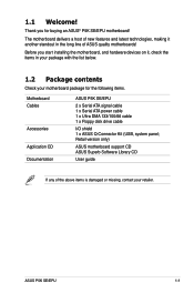
... devices on it another standout in your package with the list below. 1.2 Package contents Check your retailer. The motherboard delivers a host of new features and latest technologies, making it , check the items in the long line of the above items is damaged or missing, contact your motherboard package for buying an ASUS® P5K SE/EPU motherboard! ASUS P5K SE/EPU 1-1
... devices on it another standout in your package with the list below. 1.2 Package contents Check your retailer. The motherboard delivers a host of new features and latest technologies, making it , check the items in the long line of the above items is damaged or missing, contact your motherboard package for buying an ASUS® P5K SE/EPU motherboard! ASUS P5K SE/EPU 1-1
User Manual
Page 16
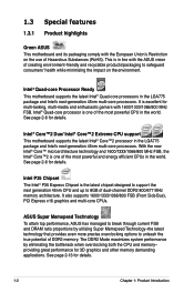
...with 1600/1333/1066/800 MHz FSB. This is excellent for details. 1-2 Chapter 1: Product Introduction 1.3 Special features 1.3.1 Product highlights Green ASUS This motherboard and its packaging comply with the European Union's Restriction on the environment. It is in the world.... ASUS Super Memspeed Technology To attain top performance, ASUS has managed to break through current FSB and DRAM ratio proportions by eliminating the bottleneck when overclocking both the ...
...with 1600/1333/1066/800 MHz FSB. This is excellent for details. 1-2 Chapter 1: Product Introduction 1.3 Special features 1.3.1 Product highlights Green ASUS This motherboard and its packaging comply with the European Union's Restriction on the environment. It is in the world.... ASUS Super Memspeed Technology To attain top performance, ASUS has managed to break through current FSB and DRAM ratio proportions by eliminating the bottleneck when overclocking both the ...
User Manual
Page 17
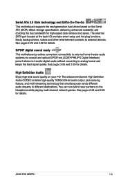
... ready This motherboard provides convenient connectivity to external home theater audio systems via coaxial and optical S/PDIF-out (SONY-PHILIPS Digital Interface) jacks.It allows to transfer digital audio without converting to external devices. You can now talk to different destinations. ASUS P5K SE/EPU 1-3 The ... for details. See pages 2-25 and 2-28 for details. Serial ATA 3.0 Gb/s technology and SATA-On-The-Go This motherboard supports the next-generation hard drives based on the headphone while playing multi-channel network games. High Definition Audio Enjoy high-end ...
... ready This motherboard provides convenient connectivity to external home theater audio systems via coaxial and optical S/PDIF-out (SONY-PHILIPS Digital Interface) jacks.It allows to transfer digital audio without converting to external devices. You can now talk to different destinations. ASUS P5K SE/EPU 1-3 The ... for details. See pages 2-25 and 2-28 for details. Serial ATA 3.0 Gb/s technology and SATA-On-The-Go This motherboard supports the next-generation hard drives based on the headphone while playing multi-channel network games. High Definition Audio Enjoy high-end ...
User Manual
Page 19
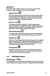
...wrong cable connections. See page 4-34 for details. Simply press the predefined hotkey to the motherboard. ASUS Q-Connector ASUS Q-Connector allows you to easily connect or disconnect the chassis front panel cables to launch ...ASUS P5K SE/EPU 1-5 See page 2-35 for details. The BIOS settings can easily see which drivers are already installed, as well as those that allows users to share and distribute their favorite settings. ASUS CrashFree BIOS 3 The ASUS CrashFree BIOS 3 allows users to convert your screen. Profile The motherboard features the ASUS O.C. ASUS O.C. ASUS...
...wrong cable connections. See page 4-34 for details. Simply press the predefined hotkey to the motherboard. ASUS Q-Connector ASUS Q-Connector allows you to easily connect or disconnect the chassis front panel cables to launch ...ASUS P5K SE/EPU 1-5 See page 2-35 for details. The BIOS settings can easily see which drivers are already installed, as well as those that allows users to share and distribute their favorite settings. ASUS CrashFree BIOS 3 The ASUS CrashFree BIOS 3 allows users to convert your screen. Profile The motherboard features the ASUS O.C. ASUS O.C. ASUS...
User Manual
Page 20
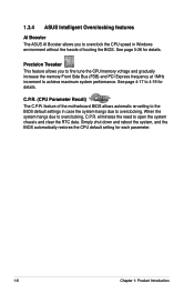
.... Simply shut down and reboot the system, and the BIOS automatically restores the CPU default setting for details. 1.3.4 ASUS Intelligent Overclocking features AI Booster The ASUS AI Booster allows you to fine tune the CPU/memory voltage and gradually increase the memory Front Side Bus (FSB)... and PCI Express frequency at 1MHz increment to achieve maximum system performance. feature of the motherboard BIOS allows automatic re-setting...
.... Simply shut down and reboot the system, and the BIOS automatically restores the CPU default setting for details. 1.3.4 ASUS Intelligent Overclocking features AI Booster The ASUS AI Booster allows you to fine tune the CPU/memory voltage and gradually increase the memory Front Side Bus (FSB)... and PCI Express frequency at 1MHz increment to achieve maximum system performance. feature of the motherboard BIOS allows automatic re-setting...
User Manual
Page 21
This chapter lists the hardware setup procedures that you have to perform when installing system components. It includes description of the jumpers and connectors on the motherboard. Chapter 2: 2 Hardware information
This chapter lists the hardware setup procedures that you have to perform when installing system components. It includes description of the jumpers and connectors on the motherboard. Chapter 2: 2 Hardware information
User Manual
Page 22
Chapter summary 2 2.1 Before you proceed 2-1 2.2 Motherboard overview 2-2 2.3 Central Processing Unit (CPU 2-6 2.4 System memory 2-13 2.5 Expansion slots 2-19 2.6 Jumpers 2-22 2.7 Connectors 2-24 ASUS P5K SE/EPU
Chapter summary 2 2.1 Before you proceed 2-1 2.2 Motherboard overview 2-2 2.3 Central Processing Unit (CPU 2-6 2.4 System memory 2-13 2.5 Expansion slots 2-19 2.6 Jumpers 2-22 2.7 Connectors 2-24 ASUS P5K SE/EPU
User Manual
Page 23
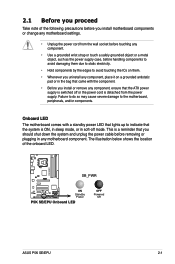
.... The illustration below shows the location of the following precautions before you install motherboard components or change any motherboard settings. • Unplug the power cord from the power supply. Onboard LED The motherboard comes with the component. • Before you should shut down the system and unplug the ...the system is ON, in sleep mode, or in any component, ensure that the ATX power supply is switched off mode. P5K SE/EPU SB_PWR ® ON Standby Power P5K SE/EPU Onboard LED OFF Powered Off ASUS P5K SE/EPU 2-1 2.1 Before you proceed Take note of the onboard LED.
.... The illustration below shows the location of the following precautions before you install motherboard components or change any motherboard settings. • Unplug the power cord from the power supply. Onboard LED The motherboard comes with the component. • Before you should shut down the system and unplug the ...the system is ON, in sleep mode, or in any component, ensure that the ATX power supply is switched off mode. P5K SE/EPU SB_PWR ® ON Standby Power P5K SE/EPU Onboard LED OFF Powered Off ASUS P5K SE/EPU 2-1 2.1 Before you proceed Take note of the onboard LED.
User Manual
Page 24
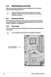
... chassis ® P5K SE/EPU 2-2 Chapter 2: Hardware information The edge with external ports goes to the rear part of the chassis as indicated in the image below. 2.2.2 Screw holes Place six (6) screws into the chassis in the correct orientation. Make sure to unplug the power cord before installing or removing the motherboard. Do not...
... chassis ® P5K SE/EPU 2-2 Chapter 2: Hardware information The edge with external ports goes to the rear part of the chassis as indicated in the image below. 2.2.2 Screw holes Place six (6) screws into the chassis in the correct orientation. Make sure to unplug the power cord before installing or removing the motherboard. Do not...
User Manual
Page 25
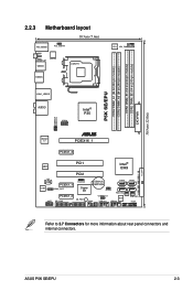
P5K SE/EPU DDR2 DIMM_A1 (64 bit,240-pin module) DDR2 DIMM_A2 (64 bit,240-pin module) DDR2 DIMM_B1 (64 bit,240-pin module) DDR2 DIMM_B2 (64 bit,240-pin module) EATXPWR 30.5cm (12.0in) 2.2.3 Motherboard layout 19.3cm (7.6in) KB_USB56 PS2_USBPW ATX12V SPDIF_O1 USB34 ESATA LGA775 EPU CPU_FAN LAN1_USB12 AUDIO Intel® P35 USB78... SB_PWR COM1 USBPW9-12 USB1112 BIOS USB910 SATA3 SATA1 CHA_FAN PANEL FLOPPY Refer to 2.7 Connectors for more information about rear panel connectors and internal connectors. ASUS P5K SE/EPU 2-3
P5K SE/EPU DDR2 DIMM_A1 (64 bit,240-pin module) DDR2 DIMM_A2 (64 bit,240-pin module) DDR2 DIMM_B1 (64 bit,240-pin module) DDR2 DIMM_B2 (64 bit,240-pin module) EATXPWR 30.5cm (12.0in) 2.2.3 Motherboard layout 19.3cm (7.6in) KB_USB56 PS2_USBPW ATX12V SPDIF_O1 USB34 ESATA LGA775 EPU CPU_FAN LAN1_USB12 AUDIO Intel® P35 USB78... SB_PWR COM1 USBPW9-12 USB1112 BIOS USB910 SATA3 SATA1 CHA_FAN PANEL FLOPPY Refer to 2.7 Connectors for more information about rear panel connectors and internal connectors. ASUS P5K SE/EPU 2-3
User Manual
Page 28
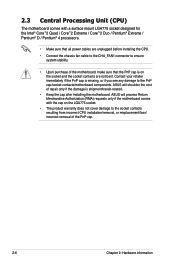
ASUS will shoulder the cost of repair only if the damage is shipment/transit-related. • Keep the cap after installing the motherboard. Contact your retailer immediately if the PnP cap is on the LGA775 socket. • The product warranty does not cover damage to ... sure that the PnP cap is missing, or if you see any damage to the PnP cap/socket contacts/motherboard components. ASUS will process Return Merchandise Authorization (RMA) requests only if the motherboard comes with a surface mount LGA775 socket designed for the Intel® Core™2 Quad / Core™2 Extreme / Core...
ASUS will shoulder the cost of repair only if the damage is shipment/transit-related. • Keep the cap after installing the motherboard. Contact your retailer immediately if the PnP cap is on the LGA775 socket. • The product warranty does not cover damage to ... sure that the PnP cap is missing, or if you see any damage to the PnP cap/socket contacts/motherboard components. ASUS will process Return Merchandise Authorization (RMA) requests only if the motherboard comes with a surface mount LGA775 socket designed for the Intel® Core™2 Quad / Core™2 Extreme / Core...

User Manual
Page 29
P5K SE/EPU ® P5K SE/EPU CPU Socket 775 Before installing the CPU, make sure that the socket box is facing towards you and the load lever is released from the ...º angle. ASUS P5K SE/EPU 2-7 To prevent damage to the socket pins, do not remove the PnP cap unless you . 2.3.1 Installing the CPU To install a CPU: 1. Retention tab A Load lever PnP cap B This side of the arrow to the left . 2. Locate the CPU socket on your thumb (A), then move it is on the motherboard.
P5K SE/EPU ® P5K SE/EPU CPU Socket 775 Before installing the CPU, make sure that the socket box is facing towards you and the load lever is released from the ...º angle. ASUS P5K SE/EPU 2-7 To prevent damage to the socket pins, do not remove the PnP cap unless you . 2.3.1 Installing the CPU To install a CPU: 1. Retention tab A Load lever PnP cap B This side of the arrow to the left . 2. Locate the CPU socket on your thumb (A), then move it is on the motherboard.
User Manual
Page 31
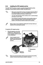
...the four fasteners match the holes on the motherboard. If you buy a boxed Intel® processor, the package includes the CPU fan and heatsink assembly. Narrow end of the groove pointing outward. (The photo shows the groove shaded for emphasis.) ASUS P5K SE/EPU 2-9 To install the CPU heatsink and fan:.... • If you purchased a separate CPU heatsink and fan assembly, make sure that you have installed the motherboard to orient each fastener with the narrow end of the groove Motherboard hole Fastener Make sure to the chassis before you install the CPU fan and heatsink assembly.
...the four fasteners match the holes on the motherboard. If you buy a boxed Intel® processor, the package includes the CPU fan and heatsink assembly. Narrow end of the groove pointing outward. (The photo shows the groove shaded for emphasis.) ASUS P5K SE/EPU 2-9 To install the CPU heatsink and fan:.... • If you purchased a separate CPU heatsink and fan assembly, make sure that you have installed the motherboard to orient each fastener with the narrow end of the groove Motherboard hole Fastener Make sure to the chassis before you install the CPU fan and heatsink assembly.
User Manual
Page 32
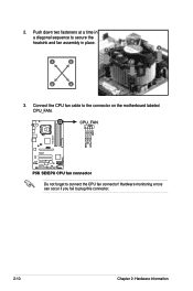
CPU_FAN P5K SE/EPU GND CPU FAN PWR CPU FAN IN CPU FAN PWM ® P5K SE/EPU CPU fan connector Do not forget to the connector on the motherboard labeled CPU_FAN. Connect the CPU fan cable to connect the CPU fan connector! B A A A B B B A 3. Hardware monitoring errors can occur if you fail to secure the heatsink and fan assembly in place. Push down two fasteners at a time in a diagonal sequence to plug this connector. 2-10 Chapter 2: Hardware information 2.
CPU_FAN P5K SE/EPU GND CPU FAN PWR CPU FAN IN CPU FAN PWM ® P5K SE/EPU CPU fan connector Do not forget to the connector on the motherboard labeled CPU_FAN. Connect the CPU fan cable to connect the CPU fan connector! B A A A B B B A 3. Hardware monitoring errors can occur if you fail to secure the heatsink and fan assembly in place. Push down two fasteners at a time in a diagonal sequence to plug this connector. 2-10 Chapter 2: Hardware information 2.


