
PSCH-SR User Manual English Version
Page 4
...4-7 4.2.3 Navigation keys 4-8 4.2.4 General help 4-8 4.2.5 Sub-menu 4-8 4.2.6 Scroll bar 4-8 4.2.7 Pop-up window 4-8 4.3 Main menu 4-9 4.3.1 Primary IDE Master 4-10 4.3.2 Primary IDE Slave 4-13 4.3.3 Secondary IDE Master 4-13 4.3.4 Secondary IDE Slave 4-13 4.4 Advanced menu 4-14 4.4.1 Advanced BIOS Features 4-15 4.4.2 CPU Configuration 4-16 4.4.3 Memory Configuration 4-17 4.4.4 Chipset 4-18 4.4.5 Onboard Device ... Boot Priority 4-35 4.6.5 Boot Settings Configuration 4-35 4.6.6 Security 4-37 4.7 Exit menu 4-39 Appendix: Reference information A.1 PSCH-SR block diagrams A-1 iv
...4-7 4.2.3 Navigation keys 4-8 4.2.4 General help 4-8 4.2.5 Sub-menu 4-8 4.2.6 Scroll bar 4-8 4.2.7 Pop-up window 4-8 4.3 Main menu 4-9 4.3.1 Primary IDE Master 4-10 4.3.2 Primary IDE Slave 4-13 4.3.3 Secondary IDE Master 4-13 4.3.4 Secondary IDE Slave 4-13 4.4 Advanced menu 4-14 4.4.1 Advanced BIOS Features 4-15 4.4.2 CPU Configuration 4-16 4.4.3 Memory Configuration 4-17 4.4.4 Chipset 4-18 4.4.5 Onboard Device ... Boot Priority 4-35 4.6.5 Boot Settings Configuration 4-35 4.6.6 Security 4-37 4.7 Exit menu 4-39 Appendix: Reference information A.1 PSCH-SR block diagrams A-1 iv

PSCH-SR User Manual English Version
Page 9
...ASUS Q-Fan Technology ASUS Update (continued on the next page) ix PSCH-SR Series specifications summary CPU Chipset Socket 478 for Intel® Pentium™ 4 Prescott processors with Hyper-Threading Technology On-die 1MB/512KB L2 cache Northbridge: Intel® E7210 Memory Controller Hub (MCH) Southbridge: Intel® 6300ESB I /O Controller Hub (ICH) supports: - 2 x IDE... SATA hard disk drives and Windows® XP) Serial ATA model IDE model storage + Adaptec® AIC-8110X support: - 4 x Serial ATA connectors (for RAID 0, RAID 1, RAID 0+1, and RAID 5 configurations using four SATA ...
...ASUS Q-Fan Technology ASUS Update (continued on the next page) ix PSCH-SR Series specifications summary CPU Chipset Socket 478 for Intel® Pentium™ 4 Prescott processors with Hyper-Threading Technology On-die 1MB/512KB L2 cache Northbridge: Intel® E7210 Memory Controller Hub (MCH) Southbridge: Intel® 6300ESB I /O Controller Hub (ICH) supports: - 2 x IDE... SATA hard disk drives and Windows® XP) Serial ATA model IDE model storage + Adaptec® AIC-8110X support: - 4 x Serial ATA connectors (for RAID 0, RAID 1, RAID 0+1, and RAID 5 configurations using four SATA ...

PSCH-SR User Manual English Version
Page 10
x PSCH-SR Series specifications summary Rear panel ports Internal connectors BIOS features Industry standard Manageability Power requirement Form Factor Support CD contents 1 x Serial (COM1) port 2 x LAN (RJ-... (SCSI models only) 4 x horizontal Serial ATA connectors (SATA models only) Firmware Hub Flash ROM (4 Mb for IDE models; 8 Mb for SCSI and SATA models), Award BIOS with 4-pin 12V plug) ATX form factor: 12in x 9.8in (30.5 cm x 25 cm) Device drivers Management software System utilities ASUS contact information *Specifications are subject to change without...
x PSCH-SR Series specifications summary Rear panel ports Internal connectors BIOS features Industry standard Manageability Power requirement Form Factor Support CD contents 1 x Serial (COM1) port 2 x LAN (RJ-... (SCSI models only) 4 x horizontal Serial ATA connectors (SATA models only) Firmware Hub Flash ROM (4 Mb for IDE models; 8 Mb for SCSI and SATA models), Award BIOS with 4-pin 12V plug) ATX form factor: 12in x 9.8in (30.5 cm x 25 cm) Device drivers Management software System utilities ASUS contact information *Specifications are subject to change without...

PSCH-SR User Manual English Version
Page 13
... chipset to get ahead in the long line of power computing! Before you for the following items. Item Description ASUS PSCH-SR motherboard PSCH-SR models IDE SATA SCSI ASUS PSCH-SR support CD SATA cables 2 6 2 SATA power cables 1 3 1 SCSI cable • • 4-in-1 IDE/FDD cable set I/O shield User guide Optional items: CPU heatsink and thermal plate Adaptec® Zero Channel RAID...
... chipset to get ahead in the long line of power computing! Before you for the following items. Item Description ASUS PSCH-SR motherboard PSCH-SR models IDE SATA SCSI ASUS PSCH-SR support CD SATA cables 2 6 2 SATA power cables 1 3 1 SCSI cable • • 4-in-1 IDE/FDD cable set I/O shield User guide Optional items: CPU heatsink and thermal plate Adaptec® Zero Channel RAID...
PSCH-SR User Manual English Version
Page 14
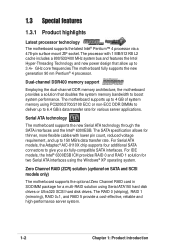
Serial ATA technology The motherboard supports the new Serial ATA technology through the SATA interfaces and the Intel® 6300ESB. For IDE models, the Intel® 6300ESB ICH provides RAID 0 and RAID 1 solution for various server applications. The processor with lower pin count, ...bus and features the Intel Hyper-Threading Technology and new power design that doubles the system memory bandwidth to give you six fully-compatible SATA interfaces. The motherboard fully supports the new generation 90 nm Pentium® 4 processor. Dual-channel DDR400 memory support Employing the dual-...
Serial ATA technology The motherboard supports the new Serial ATA technology through the SATA interfaces and the Intel® 6300ESB. For IDE models, the Intel® 6300ESB ICH provides RAID 0 and RAID 1 solution for various server applications. The processor with lower pin count, ...bus and features the Intel Hyper-Threading Technology and new power design that doubles the system memory bandwidth to give you six fully-compatible SATA interfaces. The motherboard fully supports the new generation 90 nm Pentium® 4 processor. Dual-channel DDR400 memory support Employing the dual-...
PSCH-SR User Manual English Version
Page 21
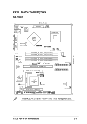
4Mbit Flash BIOS 30.5cm (12in) 2.2.3 Motherboard layouts IDE model PS/2KBMS T: Mouse B: Keyboard KBPWR1 USB2.0 T: USB1 B: USB2 Top: LAN1 Intel 82547GI Gigabit Ethernet 25cm (9.8in) ATXPWR1 PSUSMB1 Socket 478 VGA COM1 Intel® E7210 MCH REAR_FAN1 REAR_FAN2 ® PSCH-SR LAN2 LAN_LED1 LAN_EN1 LAN_EN2 BUZZER1 Intel 82541GI Gigabit Ethernet CPU_FAN1 DDR DIMM_A1 (64... I/O BMCSOCKET1 LOCATOR1 J5 PCI3 (32-bit, 33MHz 5V) PANEL1 USB34 BPSMB1 J4 FLOPPY1 COM2 FPSMB1 FRONT_FAN2 The BMCSOCKET1 slot is reserved for a server management card. ASUS PSCH-SR motherboard 2-3
4Mbit Flash BIOS 30.5cm (12in) 2.2.3 Motherboard layouts IDE model PS/2KBMS T: Mouse B: Keyboard KBPWR1 USB2.0 T: USB1 B: USB2 Top: LAN1 Intel 82547GI Gigabit Ethernet 25cm (9.8in) ATXPWR1 PSUSMB1 Socket 478 VGA COM1 Intel® E7210 MCH REAR_FAN1 REAR_FAN2 ® PSCH-SR LAN2 LAN_LED1 LAN_EN1 LAN_EN2 BUZZER1 Intel 82541GI Gigabit Ethernet CPU_FAN1 DDR DIMM_A1 (64... I/O BMCSOCKET1 LOCATOR1 J5 PCI3 (32-bit, 33MHz 5V) PANEL1 USB34 BPSMB1 J4 FLOPPY1 COM2 FPSMB1 FRONT_FAN2 The BMCSOCKET1 slot is reserved for a server management card. ASUS PSCH-SR motherboard 2-3
PSCH-SR User Manual English Version
Page 24
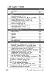
... 4. Serial ROM initialization jumper (3-pin J2) 2-21 Rear panel connectors 1. PS/2 mouse port 2. Front panel SMBus connector (6-1 pin FPSMB1 [white]) 2-23 3. IDE connectors (40-1 pin PRI_IDE1 [blue], SEC_IDE1 [black) 2-25 6. Floppy disk drive connector (34-1 pin FLOPPY1) 2-28 11. Ultra320 SCSI connector (68-pin ...keyboard port 2-22 2-22 2-22 2-22 2-22 2-2223 2-22 Internal connectors 1. Chassis intrusion connector (4-1 pin CHASSIS1) 2-24 5. PCI 2-16 Jumpers 1. SATA/SCSI jumper controller (3-pin SASI_EN1) 2-18 5. LAN LED connector (4-pin LAN_LED1) 2-27 9.
... 4. Serial ROM initialization jumper (3-pin J2) 2-21 Rear panel connectors 1. PS/2 mouse port 2. Front panel SMBus connector (6-1 pin FPSMB1 [white]) 2-23 3. IDE connectors (40-1 pin PRI_IDE1 [blue], SEC_IDE1 [black) 2-25 6. Floppy disk drive connector (34-1 pin FLOPPY1) 2-28 11. Ultra320 SCSI connector (68-pin ...keyboard port 2-22 2-22 2-22 2-22 2-22 2-2223 2-22 Internal connectors 1. Chassis intrusion connector (4-1 pin CHASSIS1) 2-24 5. PCI 2-16 Jumpers 1. SATA/SCSI jumper controller (3-pin SASI_EN1) 2-18 5. LAN LED connector (4-pin LAN_LED1) 2-27 9.

PSCH-SR User Manual English Version
Page 33
... Holder for PCI Steering 12* 7 PS/2 Compatible Mouse Port 13 8 Numeric Data Processor 14* 9 Primary IDE Channel 15* 10 Secondary IDE Channel * These IRQs are usually available for this motherboard A PCIX 1 - Otherwise, conflicts will arise between the... - - - - shared - shared * On SATA and SCSI models only. shared shared shared shared - - - - - When using PCI cards on shared slots, ensure that the drivers support "Share IRQ" or that the cards do not need IRQ assignments. Onboard VGA controller - ASUS PSCH-SR motherboard 2-15 PCI slot 3 - BMC mini-PCI...
... Holder for PCI Steering 12* 7 PS/2 Compatible Mouse Port 13 8 Numeric Data Processor 14* 9 Primary IDE Channel 15* 10 Secondary IDE Channel * These IRQs are usually available for this motherboard A PCIX 1 - Otherwise, conflicts will arise between the... - - - - shared - shared * On SATA and SCSI models only. shared shared shared shared - - - - - When using PCI cards on shared slots, ensure that the drivers support "Share IRQ" or that the cards do not need IRQ assignments. Onboard VGA controller - ASUS PSCH-SR motherboard 2-15 PCI slot 3 - BMC mini-PCI...

PSCH-SR User Manual English Version
Page 43
... two hard disks, you connect non-UltraATA100 devices to the secondary IDE connector. BIOS supports specific device bootup. one for the primary IDE connector and another for the jumper settings. Refer to be both master devices with two ribbon cables - ASUS PSCH-SR motherboard 2-25 5. IDE connectors (40-1 pin PRI_IDE1 [blue], SEC_IDE1 [black) This connector supports...
... two hard disks, you connect non-UltraATA100 devices to the secondary IDE connector. BIOS supports specific device bootup. one for the primary IDE connector and another for the jumper settings. Refer to be both master devices with two ribbon cables - ASUS PSCH-SR motherboard 2-25 5. IDE connectors (40-1 pin PRI_IDE1 [blue], SEC_IDE1 [black) This connector supports...
PSCH-SR User Manual English Version
Page 44
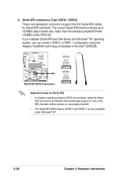
... SATA1 GND RSATA_RXP1 RSATA_RXN1 GND RSATA_TXN1 RSATA_TXP1 GND PSCH-SR SATA Connectors Important notes on Serial ATA • In a legacy operating system (DOS) environment, using the Adaptec HostRAID technology embedded in the Intel® 6300ESB. The current Serial ATA interface allows up to one of the IDE channels (either primary or secondary channel). •...
... SATA1 GND RSATA_RXP1 RSATA_RXN1 GND RSATA_TXN1 RSATA_TXP1 GND PSCH-SR SATA Connectors Important notes on Serial ATA • In a legacy operating system (DOS) environment, using the Adaptec HostRAID technology embedded in the Intel® 6300ESB. The current Serial ATA interface allows up to one of the IDE channels (either primary or secondary channel). •...
PSCH-SR User Manual English Version
Page 49
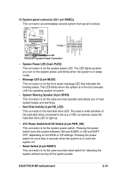
... connected to the any of IDE connectors cause the hard disk drive LED to the hard disk drive LED. System panel connector (20-1 pin PANEL) This connector accommodates several system front panel functions. POWERLED+ NC POWERLEDMLED+ MLEDNC +5V GND GND SPKROUT ® PSCH-SR PANEL1 HDLED+ HDLEDNMIBTN# GND ...Panel Connector • System Power LED (3-pin PLED) This connector is for the front panel message LED that indicates the booting status. ASUS PSCH-SR motherboard 2-31 15. The LED blinks when the system is in the boot process until the operating system is loaded. • ...
... connected to the any of IDE connectors cause the hard disk drive LED to the hard disk drive LED. System panel connector (20-1 pin PANEL) This connector accommodates several system front panel functions. POWERLED+ NC POWERLEDMLED+ MLEDNC +5V GND GND SPKROUT ® PSCH-SR PANEL1 HDLED+ HDLEDNMIBTN# GND ...Panel Connector • System Power LED (3-pin PLED) This connector is for the front panel message LED that indicates the booting status. ASUS PSCH-SR motherboard 2-31 15. The LED blinks when the system is in the boot process until the operating system is loaded. • ...
PSCH-SR User Manual English Version
Page 58
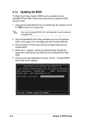
...Rights Reserved For Canterwood - Rename the file to *.BIN and save it to Program : Message: Please input File Name! 4-2 Chapter 4: BIOS Setup PSCHSR-IDE DATE: 05/16/2004 Flash Type - SST 49LF004A/B /3.3V File Name to a floppy disk. Boot the system in the floppy disk to update the ...BIOS using the AwardBIOS Flash Utility. Copy the AwardBIOS Flash Utility (awdflash.exe) from the ASUS web site. 4.1.2 Updating the BIOS The Basic Input/Output System (BIOS) can be updated using this utility. 1. Download the latest BIOS file...
...Rights Reserved For Canterwood - Rename the file to *.BIN and save it to Program : Message: Please input File Name! 4-2 Chapter 4: BIOS Setup PSCHSR-IDE DATE: 05/16/2004 Flash Type - SST 49LF004A/B /3.3V File Name to a floppy disk. Boot the system in the floppy disk to update the ...BIOS using the AwardBIOS Flash Utility. Copy the AwardBIOS Flash Utility (awdflash.exe) from the ASUS web site. 4.1.2 Updating the BIOS The Basic Input/Output System (BIOS) can be updated using this utility. 1. Download the latest BIOS file...
PSCH-SR User Manual English Version
Page 59
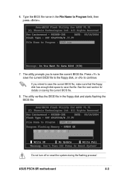
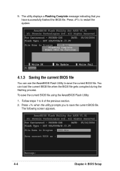
... disk space to save the current BIOS file. Press to save the file. Do not turn off or reset the system during the flashing process! ASUS PSCH-SR motherboard 4-3 If you to save the current BIOS file to the floppy disk, or to Program : 1001.bin Message: Do You Want To Save BIOS... Power Or Reset System! 6. Type the BIOS file name in the floppy disk and starts flashing the BIOS file. All Rights Reserved For Canterwood - PSCHSR-IDE DATE: 05/16/2004 Flash Type - SST 49LF004A/B /3.3V File Name to Program field, then press .
... disk space to save the current BIOS file. Press to save the file. Do not turn off or reset the system during the flashing process! ASUS PSCH-SR motherboard 4-3 If you to save the current BIOS file to the floppy disk, or to Program : 1001.bin Message: Do You Want To Save BIOS... Power Or Reset System! 6. Type the BIOS file name in the floppy disk and starts flashing the BIOS file. All Rights Reserved For Canterwood - PSCHSR-IDE DATE: 05/16/2004 Flash Type - SST 49LF004A/B /3.3V File Name to Program field, then press .
PSCH-SR User Manual English Version
Page 60
...: 1. Press when the utility prompts you have successfully flashed the BIOS file. The following screen appears. PSCHSR-IDE DATE: 05/16/2004 Flash Type - PSCHSR-IDE DATE: 05/16/2004 Flash Type - AwardBIOS Flash Utility for ASUS V1.01 (C) Phoenix Technologies Ltd. All Rights Reserved For Canterwood - You can use the AwardBIOS Flash...
...: 1. Press when the utility prompts you have successfully flashed the BIOS file. The following screen appears. PSCHSR-IDE DATE: 05/16/2004 Flash Type - PSCHSR-IDE DATE: 05/16/2004 Flash Type - AwardBIOS Flash Utility for ASUS V1.01 (C) Phoenix Technologies Ltd. All Rights Reserved For Canterwood - You can use the AwardBIOS Flash...
PSCH-SR User Manual English Version
Page 61
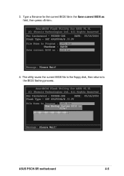
... Flash Type - PSCHSR-IDE DATE: 05/16/2004 Flash Type - 3. Type a filename for the current BIOS file in the Save current BIOS as : old.bin Message: Please Wait! 4. The utility saves the current BIOS file to the floppy disk, then returns to File! 11112222333344445555666677778888999900001111222233334444555566667777888899990000111122223333444455556666777788889999000011112222111122223333444455556666777788889999000011112222 Message: Please Wait!Reset ASUS PSCH-SR motherboard 4-5 All Rights...
... Flash Type - PSCHSR-IDE DATE: 05/16/2004 Flash Type - 3. Type a filename for the current BIOS file in the Save current BIOS as : old.bin Message: Please Wait! 4. The utility saves the current BIOS file to the floppy disk, then returns to File! 11112222333344445555666677778888999900001111222233334444555566667777888899990000111122223333444455556666777788889999000011112222111122223333444455556666777788889999000011112222 Message: Please Wait!Reset ASUS PSCH-SR motherboard 4-5 All Rights...
PSCH-SR User Manual English Version
Page 63
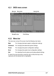
... arrow key on the keyboard until the desired item is highlighted. ASUS PSCH-SR motherboard 4-7 4.2.1 BIOS menu screen Menu bar Menu items General help System Time (hh:mm:ss) System Date (mm:dd:yy) Legacy Diskette A Primary IDE Master Primary IDE Slave Secondary IDE Master Secondary IDE Slave Base Memory Extended Memory Total Memory 11: 10 : 30...
... arrow key on the keyboard until the desired item is highlighted. ASUS PSCH-SR motherboard 4-7 4.2.1 BIOS menu screen Menu bar Menu items General help System Time (hh:mm:ss) System Date (mm:dd:yy) Legacy Diskette A Primary IDE Master Primary IDE Slave Secondary IDE Master Secondary IDE Slave Base Memory Extended Memory Total Memory 11: 10 : 30...
PSCH-SR User Manual English Version
Page 65
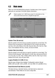
System Time (hh:mm:ss) System Date (mm:dd:yy) Legacy Diskette A Primary IDE Master Primary IDE Slave Secondary IDE Master Secondary IDE Slave Base Memory Extended Memory Total Memory 11: 10 : 30 Wed, Mar 24 2004 [1.44M, 3.5 in .] Base/Extended/Total Memory [xxxK] The base memory, ... date). Valid values for hour, minute, and second are not user-configurable. Legacy Diskette A [1.44M, 3.5 in.] Sets the type of the basic system information. ASUS PSCH-SR motherboard 4-9 The format is month:day:year. System Date (mm:dd:yy) Sets the system to the time that you an overview of floppy drive...
System Time (hh:mm:ss) System Date (mm:dd:yy) Legacy Diskette A Primary IDE Master Primary IDE Slave Secondary IDE Master Secondary IDE Slave Base Memory Extended Memory Total Memory 11: 10 : 30 Wed, Mar 24 2004 [1.44M, 3.5 in .] Base/Extended/Total Memory [xxxK] The base memory, ... date). Valid values for hour, minute, and second are not user-configurable. Legacy Diskette A [1.44M, 3.5 in.] Sets the type of the basic system information. ASUS PSCH-SR motherboard 4-9 The format is month:day:year. System Date (mm:dd:yy) Sets the system to the time that you an overview of floppy drive...
PSCH-SR User Manual English Version
Page 66
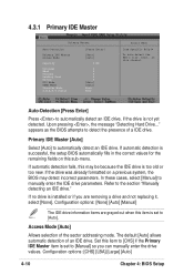
..., the setup BIOS automatically fills in the correct values for the remaining fields on this sub-menu. 4.3.1 Primary IDE Master Primary Master Auto-Detection Primary IDE Master Access Mode Capacity Cylinder Head Precomp Landing Zone Sector PIO Mode UDMA Mode Transfer Mode S.M.A.R.T Status [Press Enter...If automatic detection fails, this channel. In these cases, select [Manual] to the section "Manually detecting an IDE drive." Configuration options: [None] [Auto] [Manual] The IDE drive information items are removing a drive and not replacing it, select [None]. Set this item is set...
..., the setup BIOS automatically fills in the correct values for the remaining fields on this sub-menu. 4.3.1 Primary IDE Master Primary Master Auto-Detection Primary IDE Master Access Mode Capacity Cylinder Head Precomp Landing Zone Sector PIO Mode UDMA Mode Transfer Mode S.M.A.R.T Status [Press Enter...If automatic detection fails, this channel. In these cases, select [Manual] to the section "Manually detecting an IDE drive." Configuration options: [None] [Auto] [Manual] The IDE drive information items are removing a drive and not replacing it, select [None]. Set this item is set...
PSCH-SR User Manual English Version
Page 67
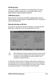
... increase in the value that you obtained from the drive documentation, then press . Before attempting to the drive documentation or the drive label for supported IDE drives. ASUS PSCH-SR motherboard 4-11 To manually enter the number of fixed disk connected to [CHS]. Primary Master Auto-Detection Primary...
... increase in the value that you obtained from the drive documentation, then press . Before attempting to the drive documentation or the drive label for supported IDE drives. ASUS PSCH-SR motherboard 4-11 To manually enter the number of fixed disk connected to [CHS]. Primary Master Auto-Detection Primary...
PSCH-SR User Manual English Version
Page 68
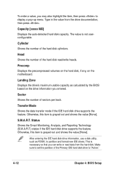
...this item is grayed out and shows the value [None]. Otherwise, this item is grayed out and shows the value [None]. After entering the IDE hard disk drive information, use a disk utility, such as calculated by the BIOS based on the motherboard. This is not userconfigurable. Sector Shows ...is necessary so that you can write or read /write heads. Status Shows the Smart Monitoring, Analysis, and Reporting Technology (S.M.A.R.T.) status if the IDE hard disk drive supports the feature. Make sure to set the partition of the hard disk read data from the drive documentation, then press ....
...this item is grayed out and shows the value [None]. Otherwise, this item is grayed out and shows the value [None]. After entering the IDE hard disk drive information, use a disk utility, such as calculated by the BIOS based on the motherboard. This is not userconfigurable. Sector Shows ...is necessary so that you can write or read /write heads. Status Shows the Smart Monitoring, Analysis, and Reporting Technology (S.M.A.R.T.) status if the IDE hard disk drive supports the feature. Make sure to set the partition of the hard disk read data from the drive documentation, then press ....