
Users Manual English
Page 1
Motherboard ROG STRIX B650E-I GAMING WIFI
Motherboard ROG STRIX B650E-I GAMING WIFI

Users Manual English
Page 3
Contents Safety information...iv About this guide...v ROG STRIX B650E-I GAMING WIFI specifications summary vi Package contents...x Installation tools and components xi Chapter 1: Product Introduction 1.1 Before you proceed 1-1 1.2 Motherboard layout 1-2 Chapter...first time 2-23 2.6 Turning off the computer 2-23 Chapter 3: BIOS and RAID Support 3.1 Knowing BIOS 3-1 3.2 BIOS setup program 3-2 3.3 ASUS EZ Flash 3 3-3 3.4 ASUS CrashFree BIOS 3 3-4 3.5 RAID configurations 3-5 Appendix Notices ...A-1 Warranty...A-10 ASUS contact information A-12 Service and Support A-12 iii
Contents Safety information...iv About this guide...v ROG STRIX B650E-I GAMING WIFI specifications summary vi Package contents...x Installation tools and components xi Chapter 1: Product Introduction 1.1 Before you proceed 1-1 1.2 Motherboard layout 1-2 Chapter...first time 2-23 2.6 Turning off the computer 2-23 Chapter 3: BIOS and RAID Support 3.1 Knowing BIOS 3-1 3.2 BIOS setup program 3-2 3.3 ASUS EZ Flash 3 3-3 3.4 ASUS CrashFree BIOS 3 3-4 3.5 RAID configurations 3-5 Appendix Notices ...A-1 Warranty...A-10 ASUS contact information A-12 Service and Support A-12 iii

Users Manual English
Page 6
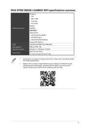
... additional USB 3.2 Gen 1 ports 1 x USB 2.0 header supports 2 additional USB 2.0 ports (continued on processors' or graphic cards' resolution. ROG STRIX B650E-I GAMING WIFI specifications summary CPU Chipset Memory Graphics Expansion Slots Storage Ethernet Wireless & Bluetooth USB AMD Socket AM5 for AMD Ryzen™ 7000 Series Desktop Processors*... * Refer to www.asus.com for memory support list. ** Non-ECC, Un-buffered DDR5 Memory supports On-Die ECC function. 1 x HDMI®...
... additional USB 3.2 Gen 1 ports 1 x USB 2.0 header supports 2 additional USB 2.0 ports (continued on processors' or graphic cards' resolution. ROG STRIX B650E-I GAMING WIFI specifications summary CPU Chipset Memory Graphics Expansion Slots Storage Ethernet Wireless & Bluetooth USB AMD Socket AM5 for AMD Ryzen™ 7000 Series Desktop Processors*... * Refer to www.asus.com for memory support list. ** Non-ECC, Un-buffered DDR5 Memory supports On-Die ECC function. 1 x HDMI®...

Users Manual English
Page 7
...) port does not support spatial audio. Rear optical S/PDIF out port - Supports up to the audio jack on the next page) vii Savitech SV3H712 AMP - ROG STRIX B650E-I GAMING WIFI specifications summary Audio Back Panel I/O Ports Internal I/O Connectors ROG SupremeFX 7.1 Surround Sound High Definition Audio CODEC ALC4080 -
...) port does not support spatial audio. Rear optical S/PDIF out port - Supports up to the audio jack on the next page) vii Savitech SV3H712 AMP - ROG STRIX B650E-I GAMING WIFI specifications summary Audio Back Panel I/O Ports Internal I/O Connectors ROG SupremeFX 7.1 Surround Sound High Definition Audio CODEC ALC4080 -

Users Manual English
Page 8
...™ button - Addressable Gen 2 header ROG Exclusive Software - GameFirst VI - Fan Xpert4 - ROG STRIX B650E-I GAMING WIFI specifications summary Internal I /O shield - Q-Slot ASUS Thermal Solution - SafeSlot - Sonic Studio III + Sonic Studio Virtual Mixer + Sonic Suite Companion - Power Saving - Two-Way AI Noise Cancellation (continued on the next page) viii VRM heatsink design ASUS EZ DIY - ProCool - Aura Creator...
...™ button - Addressable Gen 2 header ROG Exclusive Software - GameFirst VI - Fan Xpert4 - ROG STRIX B650E-I GAMING WIFI specifications summary Internal I /O shield - Q-Slot ASUS Thermal Solution - SafeSlot - Sonic Studio III + Sonic Studio Virtual Mixer + Sonic Suite Companion - Power Saving - Two-Way AI Noise Cancellation (continued on the next page) viii VRM heatsink design ASUS EZ DIY - ProCool - Aura Creator...
Users Manual English
Page 9
... for installation guide and FAQ. TPU - DIGI+ VRM - PC Cleaner MyAsus WinRAR UEFI BIOS ASUS EZ DIY - ASUS UEFI BIOS EZ Mode Dynamic OC Switcher 256 Mb Flash ROM, UEFI AMI BIOS WOL by PME, PXE Windows...inch x 6.7 inch (17 cm x 17 cm) • Specifications are subject to troubleshoot issues, optimizing product performance, integrating ASUS software, and recovery drive creation. ASUS CrashFree BIOS 3 - ROG STRIX B650E-I GAMING WIFI specifications summary Software Features BIOS Manageability Operating System Form Factor AI Suite 3 - Please scan the QR Code for the latest ...
... for installation guide and FAQ. TPU - DIGI+ VRM - PC Cleaner MyAsus WinRAR UEFI BIOS ASUS EZ DIY - ASUS UEFI BIOS EZ Mode Dynamic OC Switcher 256 Mb Flash ROM, UEFI AMI BIOS WOL by PME, PXE Windows...inch x 6.7 inch (17 cm x 17 cm) • Specifications are subject to troubleshoot issues, optimizing product performance, integrating ASUS software, and recovery drive creation. ASUS CrashFree BIOS 3 - ROG STRIX B650E-I GAMING WIFI specifications summary Software Features BIOS Manageability Operating System Form Factor AI Suite 3 - Please scan the QR Code for the latest ...
Users Manual English
Page 10
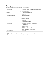
... the following items. Motherboard Cables Additional Cooling Kit Miscellaneous Documentation 1 x ROG STRIX B650E-I GAMING WIFI motherboard 2 x SATA 6Gb/s cables 1 x ROG USB2.0 splitter cable 1 x Panel cable 1 x Thermal pad for M.2 1 x ASUS Wi-Fi moving antennas 1 x Cable ties package 1 x M.2 bracket 1 x M.2 SSD screw package 1 x M.2 Q-Latch package for M.2 backplate 1 x ROG key chain 1 x ROG Strix sticker 1 x ROG Strix thank you card 1 x Rubber package for M.2 backplate 1 x User guide If...
... the following items. Motherboard Cables Additional Cooling Kit Miscellaneous Documentation 1 x ROG STRIX B650E-I GAMING WIFI motherboard 2 x SATA 6Gb/s cables 1 x ROG USB2.0 splitter cable 1 x Panel cable 1 x Thermal pad for M.2 1 x ASUS Wi-Fi moving antennas 1 x Cable ties package 1 x M.2 bracket 1 x M.2 SSD screw package 1 x M.2 Q-Latch package for M.2 backplate 1 x ROG key chain 1 x ROG Strix sticker 1 x ROG Strix thank you card 1 x Rubber package for M.2 backplate 1 x User guide If...

Users Manual English
Page 13
... Introduction 1 1.1 Before you proceed Take note of the header/jumper/connector. • For more information on installing your motherboard, please scan the QR code below: ROG STRIX B650E-I GAMING WIFI 1-1
... Introduction 1 1.1 Before you proceed Take note of the header/jumper/connector. • For more information on installing your motherboard, please scan the QR code below: ROG STRIX B650E-I GAMING WIFI 1-1
Users Manual English
Page 17
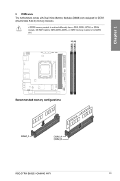
DO NOT install a DDR, DDR2, DDR3, or DDR4 memory module to the DDR5 slot. BTOB_M BTOB2_M DIMM_A DIMM_B Chapter 1 2. DIMM slots The motherboard comes with Dual Inline Memory Modules (DIMM) slots designed for DDR5 (Double Data Rate 5) memory modules. Recommended memory configurations ROG STRIX B650E-I GAMING WIFI 1-5 A DDR5 memory module is notched differently from a DDR, DDR2, DDR3, or DDR4 module.
DO NOT install a DDR, DDR2, DDR3, or DDR4 memory module to the DDR5 slot. BTOB_M BTOB2_M DIMM_A DIMM_B Chapter 1 2. DIMM slots The motherboard comes with Dual Inline Memory Modules (DIMM) slots designed for DDR5 (Double Data Rate 5) memory modules. Recommended memory configurations ROG STRIX B650E-I GAMING WIFI 1-5 A DDR5 memory module is notched differently from a DDR, DDR2, DDR3, or DDR4 module.
Users Manual English
Page 19
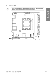
Failure to do so may cause you physical injury and damage motherboard components. Expansion slots Unplug the power cord before adding or removing expansion cards. PCIEX16 BTOB_M BTOB2_M ROG STRIX B650E-I GAMING WIFI 1-7 Chapter 1 3.
Failure to do so may cause you physical injury and damage motherboard components. Expansion slots Unplug the power cord before adding or removing expansion cards. PCIEX16 BTOB_M BTOB2_M ROG STRIX B650E-I GAMING WIFI 1-7 Chapter 1 3.

Users Manual English
Page 21
... supply plugs are designed to connect the 8-pin power plug. The system may become unstable or may not boot up if the power is inadequate. ROG STRIX B650E-I GAMING WIFI 1-9 Chapter 1 6. A ATX_12V +12V DC +12V DC +12V DC +12V DC GND GND GND GND PIN 1 A B ATX_PWR +3 Volts +12 Volts B +12 Volts +5V Standby Power OK...
... supply plugs are designed to connect the 8-pin power plug. The system may become unstable or may not boot up if the power is inadequate. ROG STRIX B650E-I GAMING WIFI 1-9 Chapter 1 6. A ATX_12V +12V DC +12V DC +12V DC +12V DC GND GND GND GND PIN 1 A B ATX_PWR +3 Volts +12 Volts B +12 Volts +5V Standby Power OK...

Users Manual English
Page 23
You can create a RAID 0 and 1 configuration through the onboard AMD B650 chipset. BA A SATA6G_1 B SATA6G_2 GND RSATA_RXP RSATA_RXN GND RSATA_TXN RSATA_TXP GND If you installed SATA storage devices to the SATA6G_1-2 ports, you to the RAID Configuration Guide. Before creating a RAID set, refer to connect SATA devices such as optical disc drives and hard disk drives via SATA cables. BTOB_M BTOB2_M Chapter 1 8. ROG STRIX B650E-I GAMING WIFI 1-11 SATA 6Gb/s ports The SATA 6Gb/s ports allow you can download the RAID Configuration Guide from the ASUS website.
You can create a RAID 0 and 1 configuration through the onboard AMD B650 chipset. BA A SATA6G_1 B SATA6G_2 GND RSATA_RXP RSATA_RXN GND RSATA_TXN RSATA_TXP GND If you installed SATA storage devices to the SATA6G_1-2 ports, you to the RAID Configuration Guide. Before creating a RAID set, refer to connect SATA devices such as optical disc drives and hard disk drives via SATA cables. BTOB_M BTOB2_M Chapter 1 8. ROG STRIX B650E-I GAMING WIFI 1-11 SATA 6Gb/s ports The SATA 6Gb/s ports allow you can download the RAID Configuration Guide from the ASUS website.
Users Manual English
Page 25
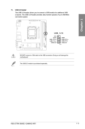
The USB 2.0 module is purchased separately. Doing so will damage the motherboard! USB_1415 NC GND USB_P14+ USB_P14USB+5V GND USB_P15+ USB_P15USB+5V PIN 1 DO NOT connect a 1394 cable to 480 Mb/s connection speed. ROG STRIX B650E-I GAMING WIFI 1-13 The USB 2.0 header provides data transfer speeds of up to the USB connectors. USB 2.0 header The USB 2.0 header allows you to connect a USB module for additional USB 2.0 ports. BTOB_M BTOB2_M Chapter 1 11.
The USB 2.0 module is purchased separately. Doing so will damage the motherboard! USB_1415 NC GND USB_P14+ USB_P14USB+5V GND USB_P15+ USB_P15USB+5V PIN 1 DO NOT connect a 1394 cable to 480 Mb/s connection speed. ROG STRIX B650E-I GAMING WIFI 1-13 The USB 2.0 header provides data transfer speeds of up to the USB connectors. USB 2.0 header The USB 2.0 header allows you to connect a USB module for additional USB 2.0 ports. BTOB_M BTOB2_M Chapter 1 11.
Users Manual English
Page 27
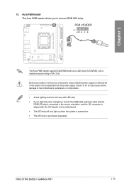
Failure to do so may cause severe damage to connect RGB LED strips. ROG STRIX B650E-I GAMING WIFI 1-15 BTOB_M BTOB2_M Chapter 1 13. RGB_HEADER PIN 1 +12V G R B The Aura RGB header supports 5050 RGB multi-color LED strips (12V/G/R/B), with the 12V header on ...
Failure to do so may cause severe damage to connect RGB LED strips. ROG STRIX B650E-I GAMING WIFI 1-15 BTOB_M BTOB2_M Chapter 1 13. RGB_HEADER PIN 1 +12V G R B The Aura RGB header supports 5050 RGB multi-color LED strips (12V/G/R/B), with the 12V header on ...
Users Manual English
Page 29
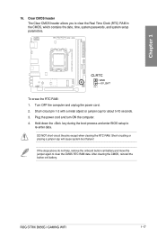
.... If the steps above do not help, remove the onboard button cell battery and move the jumper again to clear the CMOS RTC RAM data. ROG STRIX B650E-I GAMING WIFI 1-17 CLRTC GND +3V_BAT PIN 1 To erase the RTC RAM: 1.
.... If the steps above do not help, remove the onboard button cell battery and move the jumper again to clear the CMOS RTC RAM data. ROG STRIX B650E-I GAMING WIFI 1-17 CLRTC GND +3V_BAT PIN 1 To erase the RTC RAM: 1.
Users Manual English
Page 31
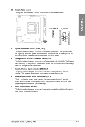
... source, or when you turn on card. • System Warning Speaker header (SPEAKER) The 4-pin header allows you to connect the Storage Device Activity LED. ROG STRIX B650E-I GAMING WIFI 1-19
... source, or when you turn on card. • System Warning Speaker header (SPEAKER) The 4-pin header allows you to connect the Storage Device Activity LED. ROG STRIX B650E-I GAMING WIFI 1-19
Users Manual English
Page 33
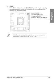
The actual cause may vary from case to case. If an error is found, the critical component's LED stays lit up until the problem is solved. ROG STRIX B650E-I GAMING WIFI 1-21 CPU (RED) DRAM (YELLOW) VGA (WHITE) BOOT (YELLOW GREEN) The Q-LEDs provide the most probable cause of an error code as a starting point for troubleshooting. Q-LEDs The Q-LEDs check key components (CPU, DRAM, VGA, and booting devices) during the motherboard booting process. BTOB_M BTOB2_M Chapter 1 21.
The actual cause may vary from case to case. If an error is found, the critical component's LED stays lit up until the problem is solved. ROG STRIX B650E-I GAMING WIFI 1-21 CPU (RED) DRAM (YELLOW) VGA (WHITE) BOOT (YELLOW GREEN) The Q-LEDs provide the most probable cause of an error code as a starting point for troubleshooting. Q-LEDs The Q-LEDs check key components (CPU, DRAM, VGA, and booting devices) during the motherboard booting process. BTOB_M BTOB2_M Chapter 1 21.
Users Manual English
Page 35
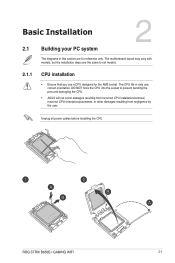
DO NOT force the CPU into the socket to prevent bending the pins and damaging the CPU. • ASUS will not cover damages resulting from incorrect CPU installation/removal, incorrect CPU orientation/placement, or other damages resulting from negligence by ... in only one correct orientation. Unplug all models. 2.1.1 CPU installation • Ensure that you use a CPU designed for reference only. Chapter 2 ROG STRIX B650E-I GAMING WIFI 2-1 The motherboard layout may vary with models, but the installation steps are for the AM5 socket. The CPU fits in this section are the same...
DO NOT force the CPU into the socket to prevent bending the pins and damaging the CPU. • ASUS will not cover damages resulting from incorrect CPU installation/removal, incorrect CPU orientation/placement, or other damages resulting from negligence by ... in only one correct orientation. Unplug all models. 2.1.1 CPU installation • Ensure that you use a CPU designed for reference only. Chapter 2 ROG STRIX B650E-I GAMING WIFI 2-1 The motherboard layout may vary with models, but the installation steps are for the AM5 socket. The CPU fits in this section are the same...
Users Manual English
Page 37
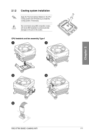
We recommend using AM5 compatible coolers with stock AM5 backplate to prevent potential damages to the CPU cooling system and CPU before you install the cooling system, if necessary. 2.1.2 Cooling system installation Apply the Thermal Interface Material to the pins in the socket. CPU heatsink and fan assembly Type 1 Chapter 2 ROG STRIX B650E-I GAMING WIFI 2-3
We recommend using AM5 compatible coolers with stock AM5 backplate to prevent potential damages to the CPU cooling system and CPU before you install the cooling system, if necessary. 2.1.2 Cooling system installation Apply the Thermal Interface Material to the pins in the socket. CPU heatsink and fan assembly Type 1 Chapter 2 ROG STRIX B650E-I GAMING WIFI 2-3
Users Manual English
Page 39
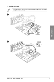
To install an AIO cooler If you wish to install an AIO cooler, we recommend installing the AIO cooler after installing the motherboard into the chassis. AIO_PUMP CPU_FAN Chapter 2 ROG STRIX B650E-I GAMING WIFI 2-5
To install an AIO cooler If you wish to install an AIO cooler, we recommend installing the AIO cooler after installing the motherboard into the chassis. AIO_PUMP CPU_FAN Chapter 2 ROG STRIX B650E-I GAMING WIFI 2-5


