
User Guide
Page 11
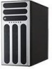
ASUS TS500-E6/PS4 Product introduction Chapter 1 This chapter describes the general features of the server, including sections on front panel and rear panel specifications.
ASUS TS500-E6/PS4 Product introduction Chapter 1 This chapter describes the general features of the server, including sections on front panel and rear panel specifications.

User Guide
Page 12
...retailer. 1.2 Serial number label Before requesting support from the ASUS Technical Support team, you must take note of the above items is damaged or missing, contact your problems. TS500-E6/PS4 xxxxxxxxxxxx 1-2 Chapter 1: Product introduction 1.1 System package contents ...Check your system package for the following items. Model Name TS500-E6/PS4 Chassis ASUS T50A Pedestal 5U Rackmount Chassis Motherboard ASUS Z8NA-D6 Server Board Component 1 x...
...retailer. 1.2 Serial number label Before requesting support from the ASUS Technical Support team, you must take note of the above items is damaged or missing, contact your problems. TS500-E6/PS4 xxxxxxxxxxxx 1-2 Chapter 1: Product introduction 1.1 System package contents ...Check your system package for the following items. Model Name TS500-E6/PS4 Chassis ASUS T50A Pedestal 5U Rackmount Chassis Motherboard ASUS Z8NA-D6 Server Board Component 1 x...

User Guide
Page 13
... Bays A or S = hot- 4 x Hot-swap 3.5" HDD Bays swappable (continued on the next page) ASUS TS500-E6/PS4 1-3 Model Name TS500-E6/PS4 2 x Socket LGA1366 Processor / System Bus - Supports RAID 0,1,5,10 & 6 ASUS PIKE 6480 SAS RAID card - 1.3 System specifications The ASUS TS500-E6/PS4 is a 5U barebone server system featuring the ASUS Z8NA-D6 server board. Supports RAID 0, 1 & 1E SAS Controller...
... Bays A or S = hot- 4 x Hot-swap 3.5" HDD Bays swappable (continued on the next page) ASUS TS500-E6/PS4 1-3 Model Name TS500-E6/PS4 2 x Socket LGA1366 Processor / System Bus - Supports RAID 0,1,5,10 & 6 ASUS PIKE 6480 SAS RAID card - 1.3 System specifications The ASUS TS500-E6/PS4 is a 5U barebone server system featuring the ASUS Z8NA-D6 server board. Supports RAID 0, 1 & 1E SAS Controller...

User Guide
Page 15
ASUS TS500-E6/PS4 1-5 For future installation of 5.25-inch devices, two drive bays are located on the front panel. 1.4 Front panel features The barebone server displays a simple yet ...
ASUS TS500-E6/PS4 1-5 For future installation of 5.25-inch devices, two drive bays are located on the front panel. 1.4 Front panel features The barebone server displays a simple yet ...

User Guide
Page 17
Optical drive (optional) 7. 2 x 5.25-inch drive bays 8. 4-bay HDD module 9. SATA/SAS backplane board 10. 80mm x 38mm system fan (hidden) Turn off the system power and detach the power supply before removing or replacing any system component. *WARNING HAZARDOUS MOVING PARTS KEEP FINGERS AND OTHER BODY PARTS AWAY ASUS TS500-E6/PS4 1-7 Expansion card locks 6. Chassis intrusion switch 5. 1.6 Internal features The barebone server includes the basic components as shown. 1 6 7 2 9 8 3 4 10 5 1. Power supply unit: 2. 120mm x 38mm system fan 3. ASUS Z8NA-D6 Server Board 4.
Optical drive (optional) 7. 2 x 5.25-inch drive bays 8. 4-bay HDD module 9. SATA/SAS backplane board 10. 80mm x 38mm system fan (hidden) Turn off the system power and detach the power supply before removing or replacing any system component. *WARNING HAZARDOUS MOVING PARTS KEEP FINGERS AND OTHER BODY PARTS AWAY ASUS TS500-E6/PS4 1-7 Expansion card locks 6. Chassis intrusion switch 5. 1.6 Internal features The barebone server includes the basic components as shown. 1 6 7 2 9 8 3 4 10 5 1. Power supply unit: 2. 120mm x 38mm system fan 3. ASUS Z8NA-D6 Server Board 4.
User Guide
Page 19
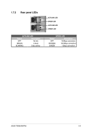
1.7.2 Rear panel LEDs ACT/LINK LED Status Description OFF No link GREEN Linked BLINKING Data activity ACT/LINK LED SPEED LED ACT/LINK LED SPEED LED SPEED LED Status Description OFF 10 Mbps connection ORANGE 100 Mbps connection GREEN 1 Gbps connection ASUS TS500-E6/PS4 1-9
1.7.2 Rear panel LEDs ACT/LINK LED Status Description OFF No link GREEN Linked BLINKING Data activity ACT/LINK LED SPEED LED ACT/LINK LED SPEED LED SPEED LED Status Description OFF 10 Mbps connection ORANGE 100 Mbps connection GREEN 1 Gbps connection ASUS TS500-E6/PS4 1-9
User Guide
Page 21
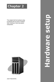
ASUS TS500-E6/PS4 Hardware setup Chapter 2 This chapter lists the hardware setup procedures that you have to perform when installing or removing system components.
ASUS TS500-E6/PS4 Hardware setup Chapter 2 This chapter lists the hardware setup procedures that you have to perform when installing or removing system components.
User Guide
Page 23
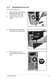
Match and insert the lower sliding edge of the side cover to the chassis. 3. Drive in place. 1 3 4. Position the side cover to the corresponding chassis edge. 2. Slide the side cover toward the front panel until it snaps in the two screws you removed earlier to secure the side cover. 4 ASUS TS500-E6/PS4 4 2-3 2.1.2 Reinstalling the side cover To reinstall the side cover: 1.
Match and insert the lower sliding edge of the side cover to the chassis. 3. Drive in place. 1 3 4. Position the side cover to the corresponding chassis edge. 2. Slide the side cover toward the front panel until it snaps in the two screws you removed earlier to secure the side cover. 4 ASUS TS500-E6/PS4 4 2-3 2.1.2 Reinstalling the side cover To reinstall the side cover: 1.
User Guide
Page 25
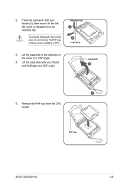
Retention tab A B Load lever 3. Lift the load plate with your thumb and forefinger to the left (B) until it is released from the CPU socket. Remove the PnP cap from the retention tab. PnP cap ASUS TS500-E6/PS4 2-5 To prevent damage to a 135º angle. 4. Lift the load lever in the direction of the arrow to the socket pins, do not remove the PnP cap unless you are installing a CPU. Press the load lever with your thumb (A), then move it to a 100º angle. 2. Load plate 4 3 5.
Retention tab A B Load lever 3. Lift the load plate with your thumb and forefinger to the left (B) until it is released from the CPU socket. Remove the PnP cap from the retention tab. PnP cap ASUS TS500-E6/PS4 2-5 To prevent damage to a 135º angle. 4. Lift the load lever in the direction of the arrow to the socket pins, do not remove the PnP cap unless you are installing a CPU. Press the load lever with your thumb (A), then move it to a 100º angle. 2. Load plate 4 3 5.

User Guide
Page 27
... to rear panel of the installed CPU, ensuring that the four screws match the holes on the support plate, and the arrow on the motherboard. ASUS TS500-E6/PS4 2-7 Hardware monitoring errors can occur if you fail to the motherboard. Do not forget to completely secure the CPU heatsink and fan. 3. Place the...
... to rear panel of the installed CPU, ensuring that the four screws match the holes on the support plate, and the arrow on the motherboard. ASUS TS500-E6/PS4 2-7 Hardware monitoring errors can occur if you fail to the motherboard. Do not forget to completely secure the CPU heatsink and fan. 3. Place the...

User Guide
Page 29
...the dual-channel or triple-channel configuration. The system maps the total size of 256 Mb (32MB) chips or less (Memory chip capacity counts in Megabit, 8 Megabit/Mb = 1 Megabyte/MB). For effective use of the following: - ASUS TS500-E6/PS4 2-9 Use a maximum of 3GB system memory if you are using the memory configurations in... 3 DIMMs DIMM_B1 -- For more memory on 32-bit Windows OS, when you install 4GB or more details, refer to install 4GB or more on the ASUS web site. • You may install 1 GB, 2 GB, 4 GB, and 8GB registered DDR3 DIMMs with ECC or 1GB, 2GB and 4GB unbuffered ...
...the dual-channel or triple-channel configuration. The system maps the total size of 256 Mb (32MB) chips or less (Memory chip capacity counts in Megabit, 8 Megabit/Mb = 1 Megabyte/MB). For effective use of the following: - ASUS TS500-E6/PS4 2-9 Use a maximum of 3GB system memory if you are using the memory configurations in... 3 DIMMs DIMM_B1 -- For more memory on 32-bit Windows OS, when you install 4GB or more details, refer to install 4GB or more on the ASUS web site. • You may install 1 GB, 2 GB, 4 GB, and 8GB registered DDR3 DIMMs with ECC or 1GB, 2GB and 4GB unbuffered ...

User Guide
Page 31
...��e�c�h��a�s�s�is� side rail. 2. Hook the other side of the front panel assembly to the chassis. 2. ASUS TS500-E6/PS4 2-11 Shift the hooked tabs and take off the front bezel. 2.4.2 Reinstalling the front panel assembly To reinstall the front panel assembly: 1. Swing the...
...��e�c�h��a�s�s�is� side rail. 2. Hook the other side of the front panel assembly to the chassis. 2. ASUS TS500-E6/PS4 2-11 Shift the hooked tabs and take off the front bezel. 2.4.2 Reinstalling the front panel assembly To reinstall the front panel assembly: 1. Swing the...

User Guide
Page 33
... is free of HDD module cage you to the SATA/SAS backplane on the HDD module cage. Insert the HDD module cage into the bay. 2 4. ASUS TS500-E6/PS4 5 2-13 2.6 SATA/SAS hard disk drives The hard disk drive module cage on the front panel, including externally removable trays for mounting either SATA...
... is free of HDD module cage you to the SATA/SAS backplane on the HDD module cage. Insert the HDD module cage into the bay. 2 4. ASUS TS500-E6/PS4 5 2-13 2.6 SATA/SAS hard disk drives The hard disk drive module cage on the front panel, including externally removable trays for mounting either SATA...
User Guide
Page 35
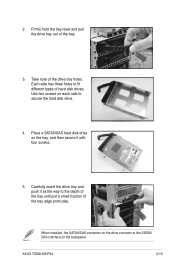
... drive on each side to fit different types of the drive tray holes. 2. Each side has three holes to secure the hard disk drive. 4. ASUS TS500-E6/PS4 2-15 Carefully insert the drive tray and push it with four screws. 5. Firmly hold the tray lever and pull the drive tray out of the...
... drive on each side to fit different types of the drive tray holes. 2. Each side has three holes to secure the hard disk drive. 4. ASUS TS500-E6/PS4 2-15 Carefully insert the drive tray and push it with four screws. 5. Firmly hold the tray lever and pull the drive tray out of the...

User Guide
Page 37
... card is designed with it and make the necessary hardware settings for you wish to install or remove an expansion card in the right figure. ASUS TS500-E6/PS4 2-17 Failure to do so may cause severe damage to unplug the power cord before installing or removing expansion cards. Ensure to the motherboard...
... card is designed with it and make the necessary hardware settings for you wish to install or remove an expansion card in the right figure. ASUS TS500-E6/PS4 2-17 Failure to do so may cause severe damage to unplug the power cord before installing or removing expansion cards. Ensure to the motherboard...

User Guide
Page 39
... slot on the PIKE RAID card slot. 4. Snap the I Button before using PIKE 1078 functions. Ensure that it is completely seated on the motherboard. 2. ASUS TS500-E6/PS4 2-19 For PIKE 1064E, connect the cable to install I Button in place. Connect the SAS cable to install an optional i Button on the motherboard. 3. For...
... slot on the PIKE RAID card slot. 4. Snap the I Button before using PIKE 1078 functions. Ensure that it is completely seated on the motherboard. 2. ASUS TS500-E6/PS4 2-19 For PIKE 1064E, connect the cable to install I Button in place. Connect the SAS cable to install an optional i Button on the motherboard. 3. For...

User Guide
Page 41
Turn on BIOS setup. 2. ASUS TS500-E6/PS4 2-21 Refer to the card. Install the software drivers for ISA or PCI devices. See Chapter 5 for information on the system and change the necessary ...
Turn on BIOS setup. 2. ASUS TS500-E6/PS4 2-21 Refer to the card. Install the software drivers for ISA or PCI devices. See Chapter 5 for information on the system and change the necessary ...

User Guide
Page 43
... 4 Front side connector HDD1 HDD2 HDD3 HDD4 Back side connector CON�1 CON�2 CON�3 CON�4 ASUS TS500-E6/PS4 2-23 2.8.2 SATA/SAS backplane connections A SATA/SAS backplane comes pre-installed in the TS500-E6. This side includes four SATA/SAS connectors for the hot swap drive trays. The LEDs on the...
... 4 Front side connector HDD1 HDD2 HDD3 HDD4 Back side connector CON�1 CON�2 CON�3 CON�4 ASUS TS500-E6/PS4 2-23 2.8.2 SATA/SAS backplane connections A SATA/SAS backplane comes pre-installed in the TS500-E6. This side includes four SATA/SAS connectors for the hot swap drive trays. The LEDs on the...
User Guide
Page 45
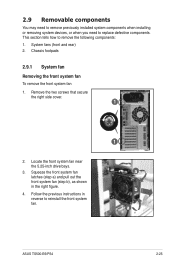
... 1. Squeeze the front system fan latches (step a) and pull out the front system fan (step b), as shown in reverse to reinstall the front system fan. 1 a b a ASUS TS500-E6/PS4 2-25 System fans (front and rear) 2. Remove the two screws that secure the right side cover. 1 2. This section tells how to replace defective components.
... 1. Squeeze the front system fan latches (step a) and pull out the front system fan (step b), as shown in reverse to reinstall the front system fan. 1 a b a ASUS TS500-E6/PS4 2-25 System fans (front and rear) 2. Remove the two screws that secure the right side cover. 1 2. This section tells how to replace defective components.

User Guide
Page 47
Repeat step 1 and 2 to the "Rackmount Kit" user guide for stability. You need to remove these footpads if you wish to install the system to a rack (Refer to Chapter 3: Installation options of the chassis for instructions) To remove the footpads 1. Lay the system chassis on its side. 2. Remove the footpad by rotating it counterclockwise with four footpads attached to the bottom of this user guide, and to remove the other three footpads. 2.9.2 Chassis footpads The barebone server system is shipped with a Philips (cross) screwdriver. 3. ASUS TS500-E6/PS4 2-27
Repeat step 1 and 2 to the "Rackmount Kit" user guide for stability. You need to remove these footpads if you wish to install the system to a rack (Refer to Chapter 3: Installation options of the chassis for instructions) To remove the footpads 1. Lay the system chassis on its side. 2. Remove the footpad by rotating it counterclockwise with four footpads attached to the bottom of this user guide, and to remove the other three footpads. 2.9.2 Chassis footpads The barebone server system is shipped with a Philips (cross) screwdriver. 3. ASUS TS500-E6/PS4 2-27