
User Guide
Page 3
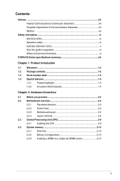
... guide is organized xi Where to find more information xi Z10PA-D8 Series specifications summary xiii Chapter 1: Product Introduction 1.1 Welcome!...1-2 1.2 Package contents 1-2 1.3 Serial number label 1-3 1.4 Special features 1-3 1.4.1 Product highlights 1-3 1.4.2 Innovative ASUS features 1-4 Chapter 2: Hardware Information 2.1 Before you proceed 2-2 2.2 Motherboard overview 2-3 2.2.1 Placement direction 2-3 2.2.2 Screw holes 2-3 2.2.3 Motherboard layout 2-4 2.2.4 Layout contents 2-6 2.3 Central Processing Unit (CPU 2-8 2.3.1 Installing the CPU...
... guide is organized xi Where to find more information xi Z10PA-D8 Series specifications summary xiii Chapter 1: Product Introduction 1.1 Welcome!...1-2 1.2 Package contents 1-2 1.3 Serial number label 1-3 1.4 Special features 1-3 1.4.1 Product highlights 1-3 1.4.2 Innovative ASUS features 1-4 Chapter 2: Hardware Information 2.1 Before you proceed 2-2 2.2 Motherboard overview 2-3 2.2.1 Placement direction 2-3 2.2.2 Screw holes 2-3 2.2.3 Motherboard layout 2-4 2.2.4 Layout contents 2-6 2.3 Central Processing Unit (CPU 2-8 2.3.1 Installing the CPU...

User Guide
Page 9
... product in municipal waste. This symbol of electronic products. Contact a qualified service technician or your area. DO NOT throw the motherboard in municipal waste. Check local regulations for the devices are unplugged before the signal cables are using an adapter or extension cord....are not sure about the voltage of the electrical outlet you add a device. • Before connecting or removing signal cables from the motherboard, ensure that all cables are correctly connected and the power cables are unplugged. • Seek professional assistance before using , contact your...
... product in municipal waste. This symbol of electronic products. Contact a qualified service technician or your area. DO NOT throw the motherboard in municipal waste. Check local regulations for the devices are unplugged before the signal cables are using an adapter or extension cord....are not sure about the voltage of the electrical outlet you add a device. • Before connecting or removing signal cables from the motherboard, ensure that all cables are correctly connected and the power cables are unplugged. • Seek professional assistance before using , contact your...

User Guide
Page 11
... About this guide is organized This user guide contains the following sources for additional information and for product and software updates. 1. ASUS websites The ASUS website provides updated information on the motherboard. • Chapter 3: Powering up This chapter describes the power up , creating, and configuring RAID sets using the available utilities. • Chapter...
... About this guide is organized This user guide contains the following sources for additional information and for product and software updates. 1. ASUS websites The ASUS website provides updated information on the motherboard. • Chapter 3: Powering up This chapter describes the power up , creating, and configuring RAID sets using the available utilities. • Chapter...
User Guide
Page 15
Chapter 1: Product Introduction Product introduction This chapter describes the motherboard features and the new technologies it supports. 1
Chapter 1: Product Introduction Product introduction This chapter describes the motherboard features and the new technologies it supports. 1

User Guide
Page 16
...long line of the above items is damaged or missing, contact your motherboard package for buying an ASUS® Z10PA-D8 Series motherboard! Congratulations and thank you start installing the motherboard and hardware devices on PCI-E slot 2/3/4/5. 1-2 Chapter 1: Product introduction... ConnectX-3 FDR card Dual port 10G SFP+ Ethernet Adapter Single port 10G SFP+ Ethernet Adapter The ASUS PIKE 3008, PIKE 3108, and PEM-FDR cards must be installed on it another standout in your... Packaging Quantity 1 piece per carton 10 pieces per carton If any of ASUS quality motherboards! 1.1 Welcome!
...long line of the above items is damaged or missing, contact your motherboard package for buying an ASUS® Z10PA-D8 Series motherboard! Congratulations and thank you start installing the motherboard and hardware devices on PCI-E slot 2/3/4/5. 1-2 Chapter 1: Product introduction... ConnectX-3 FDR card Dual port 10G SFP+ Ethernet Adapter Single port 10G SFP+ Ethernet Adapter The ASUS PIKE 3008, PIKE 3108, and PEM-FDR cards must be installed on it another standout in your... Packaging Quantity 1 piece per carton 10 pieces per carton If any of ASUS quality motherboards! 1.1 Welcome!

User Guide
Page 17
...state. DDR4 memory support The motherboard supports DDR4 memory that the standard VR solutions cannot provide. Z10PA-D8 Series 1-3 1.3 Serial number label Before requesting support from the ASUS Technical Support team, you must take note of the motherboard's serial number containing 12 characters...million transfers per second). Next Generation of up to your problems. Z10PA-D8 Series xxS2xxxxxxxx Made in China 合格 1.4 Special features 1.4.1 Product highlights Latest Processor Technology The motherboard supports Intel Xeon® processor E5-2600 V3 product family which...
...state. DDR4 memory support The motherboard supports DDR4 memory that the standard VR solutions cannot provide. Z10PA-D8 Series 1-3 1.3 Serial number label Before requesting support from the ASUS Technical Support team, you must take note of the motherboard's serial number containing 12 characters...million transfers per second). Next Generation of up to your problems. Z10PA-D8 Series xxS2xxxxxxxx Made in China 合格 1.4 Special features 1.4.1 Product highlights Latest Processor Technology The motherboard supports Intel Xeon® processor E5-2600 V3 product family which...
User Guide
Page 18
...with the last generation, it also reduces the TDP, supports USB 3.0 with up to PCIe 2.0 devices. Serial ATA III technology The motherboard supports the Serial ATA III technology through the Serial ATA interface and Intel® C612 chipset, delivering up to 10 SATA III ports..., and seamless transition with two Gigabit LAN controllers and ports which provide a total solution for critical components. 1.4.2 Innovative ASUS features ASUS Fan Speed control technology The ASUS Fan Speed control technology smartly adjusts the fan speeds according to the system loading to Gigabit bandwidth.
...with the last generation, it also reduces the TDP, supports USB 3.0 with up to PCIe 2.0 devices. Serial ATA III technology The motherboard supports the Serial ATA III technology through the Serial ATA interface and Intel® C612 chipset, delivering up to 10 SATA III ports..., and seamless transition with two Gigabit LAN controllers and ports which provide a total solution for critical components. 1.4.2 Innovative ASUS features ASUS Fan Speed control technology The ASUS Fan Speed control technology smartly adjusts the fan speeds according to the system loading to Gigabit bandwidth.
User Guide
Page 19
Chapter 2: Hardware Information Hardware Information This chapter lists the hardware setup procedures that you have to perform when installing system components. It includes description of the jumpers and connectors on the motherboard. 2
Chapter 2: Hardware Information Hardware Information This chapter lists the hardware setup procedures that you have to perform when installing system components. It includes description of the jumpers and connectors on the motherboard. 2
User Guide
Page 20
2.1 Before you proceed Take note of the following precautions before you install any motherboard component or change any motherboard settings. • Unplug the power cord from the wall socket before touching any component. • Use a grounded wrist strap or touch a safely ...such as the power supply case, before handling components to avoid damaging them due to static electricity. • Hold components by the edges to the motherboard, peripherals, and/or components. 2-2 Chapter 2: Hardware information Failure to do so may cause severe damage to avoid touching the ICs on them. •...
2.1 Before you proceed Take note of the following precautions before you install any motherboard component or change any motherboard settings. • Unplug the power cord from the wall socket before touching any component. • Use a grounded wrist strap or touch a safely ...such as the power supply case, before handling components to avoid damaging them due to static electricity. • Hold components by the edges to the motherboard, peripherals, and/or components. 2-2 Chapter 2: Hardware information Failure to do so may cause severe damage to avoid touching the ICs on them. •...
User Guide
Page 21
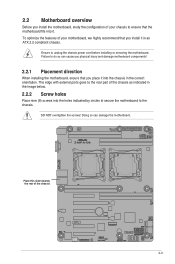
...can cause you physical injury and damage motherboard components! 2.2.1 Placement direction When installing the motherboard, ensure that the motherboard fits into it. DO NOT overtighten the screws! 2.2 Motherboard overview Before you install the motherboard, study the configuration of your motherboard, we highly recommend that you install ... holes Place nine (9) screws into the holes indicated by circles to secure the motherboard to unplug the chassis power cord before installing or removing the motherboard. Ensure to the chassis. Place this side towards the rear of your chassis to...
...can cause you physical injury and damage motherboard components! 2.2.1 Placement direction When installing the motherboard, ensure that the motherboard fits into it. DO NOT overtighten the screws! 2.2 Motherboard overview Before you install the motherboard, study the configuration of your motherboard, we highly recommend that you install ... holes Place nine (9) screws into the holes indicated by circles to secure the motherboard to unplug the chassis power cord before installing or removing the motherboard. Ensure to the chassis. Place this side towards the rear of your chassis to...
User Guide
Page 22
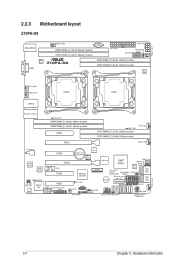
2.2.3 Motherboard layout Z10PA-D8 2-4 Chapter 2: Hardware information
2.2.3 Motherboard layout Z10PA-D8 2-4 Chapter 2: Hardware information
User Guide
Page 26
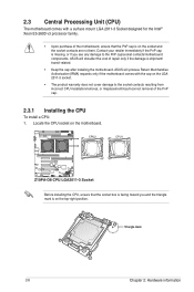
... are not bent. ASUS will shoulder the cost of the PnP cap. 2.3.1 Installing the CPU To install a CPU: 1. Locate the CPU socket on the LGA 2011-3 socket. • The product warranty does not cover damage to the PnP cap/socket contacts/motherboard components. Before installing ... CPU, ensure that the PnP cap is shipment/ transit-related. • Keep the cap after installing the motherboard. ASUS will process Return Merchandise Authorization (RMA) requests only if the motherboard comes with a surface mount LGA 2011-3 Socket designed for the Intel® Xeon E5-2600 v3 processor family...
... are not bent. ASUS will shoulder the cost of the PnP cap. 2.3.1 Installing the CPU To install a CPU: 1. Locate the CPU socket on the LGA 2011-3 socket. • The product warranty does not cover damage to the PnP cap/socket contacts/motherboard components. Before installing ... CPU, ensure that the PnP cap is shipment/ transit-related. • Keep the cap after installing the motherboard. ASUS will process Return Merchandise Authorization (RMA) requests only if the motherboard comes with a surface mount LGA 2011-3 Socket designed for the Intel® Xeon E5-2600 v3 processor family...
User Guide
Page 29
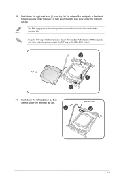
Push down the right load lever (I) ensuring that the edge of the load plate when the right load lever is fixed and tucked securely under the lever (J) then insert the right load lever under the retention tab (M). ASUS will process Return Merchandise Authorization (RMA) requests only if the motherboard comes with the PnP cap on the LGA 2011 socket. Keep the PnP cap. The PnP cap pops out of the load plate is inserted into the retention tab. PnP cap 11. 10. Push down the left load lever (L) then insert it under the retention tab (K). Retention tab 2-11
Push down the right load lever (I) ensuring that the edge of the load plate when the right load lever is fixed and tucked securely under the lever (J) then insert the right load lever under the retention tab (M). ASUS will process Return Merchandise Authorization (RMA) requests only if the motherboard comes with the PnP cap on the LGA 2011 socket. Keep the PnP cap. The PnP cap pops out of the load plate is inserted into the retention tab. PnP cap 11. 10. Push down the left load lever (L) then insert it under the retention tab (K). Retention tab 2-11
User Guide
Page 30
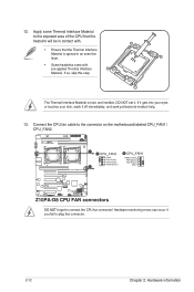
... Interface Material is toxic and inedible. Connect the CPU fan cable to connect the CPU fan connector! DO NOT forget to the connector on the motherboard labeled CPU_FAN1 / CPU_FAN2. If it gets into your eyes or touches your skin, wash it . Apply some Thermal Interface Material to plug this step. DO...
... Interface Material is toxic and inedible. Connect the CPU fan cable to connect the CPU fan connector! DO NOT forget to the connector on the motherboard labeled CPU_FAN1 / CPU_FAN2. If it gets into your eyes or touches your skin, wash it . Apply some Thermal Interface Material to plug this step. DO...
User Guide
Page 31
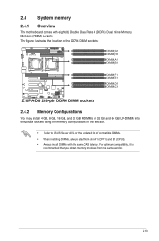
2.4 System memory 2.4.1 Overview The motherboard comes with the same CAS latency. For optimum compatibility, it is recommended that you obtain memory modules from slot A1 (CPU1) and E1 (CPU2). • ... 32 GB RDIMMs or 32 GB and 64 GB LR-DIMMs into the DIMM sockets using the memory configurations in this section. • Refer to ASUS Server AVL for the updated list of compatible DIMMs. • When installing DIMMs, always start from the same vendor. 2-13
2.4 System memory 2.4.1 Overview The motherboard comes with the same CAS latency. For optimum compatibility, it is recommended that you obtain memory modules from slot A1 (CPU1) and E1 (CPU2). • ... 32 GB RDIMMs or 32 GB and 64 GB LR-DIMMs into the DIMM sockets using the memory configurations in this section. • Refer to ASUS Server AVL for the updated list of compatible DIMMs. • When installing DIMMs, always start from the same vendor. 2-13
User Guide
Page 33
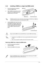
... the DIMM into the socket. Remove the DIMM from a single clip DIMM socket 1. Align a DIMM on the socket such that it flips out with the motherboard package. • Refer to avoid damaging the DIMM. 3. Press the retaining clip outward to unlock the DIMM socket. 2.4.3 Installing a DIMM on the socket. DO NOT...
... the DIMM into the socket. Remove the DIMM from a single clip DIMM socket 1. Align a DIMM on the socket such that it flips out with the motherboard package. • Refer to avoid damaging the DIMM. 3. Press the retaining clip outward to unlock the DIMM socket. 2.4.3 Installing a DIMM on the socket. DO NOT...

User Guide
Page 34
...describe the slots and the expansion cards that came with it by adjusting the software settings. 1. Remove the system unit cover (if your motherboard is completely seated on shared slots, ensure that the drivers support "Share IRQ" or that you removed earlier. 6. Keep the screw ...any. Before installing the expansion card, read the documentation that they support. 2.5 Expansion slots In the future, you physical injury and damage motherboard components. 2.5.1 Installing an expansion card To install an expansion card: 1. Assign an IRQ to unplug the power cord before adding or removing expansion...
...describe the slots and the expansion cards that came with it by adjusting the software settings. 1. Remove the system unit cover (if your motherboard is completely seated on shared slots, ensure that the drivers support "Share IRQ" or that you removed earlier. 6. Keep the screw ...any. Before installing the expansion card, read the documentation that they support. 2.5 Expansion slots In the future, you physical injury and damage motherboard components. 2.5.1 Installing an expansion card To install an expansion card: 1. Assign an IRQ to unplug the power cord before adding or removing expansion...
User Guide
Page 37
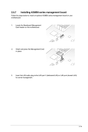
2.5.7 Installing ASMB8 series management board Follow the steps below to the LAN port 3 (dedicated LAN) or LAN port (shared LAN) for server management. 2-19 Orient and press the Management Card in place. 3. Insert the LAN cable plug to install an optional ASMB8 series management board on the motherboard. 2. Locate the Baseboard Management Card header on your motherboard. 1.
2.5.7 Installing ASMB8 series management board Follow the steps below to the LAN port 3 (dedicated LAN) or LAN port (shared LAN) for server management. 2-19 Orient and press the Management Card in place. 3. Insert the LAN cable plug to install an optional ASMB8 series management board on the motherboard. 2. Locate the Baseboard Management Card header on your motherboard. 1.
User Guide
Page 38
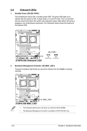
... green LED lights up to Z10PA-D8 SKU only. 2-20 Chapter 2: Hardware information This is a reminder that the system is available to indicate that you install the ASUS ASMB8. • The Baseboard Management Controller is ON, in sleep mode, or in any motherboard component. Standby Power LED (SB_PWR1) The motherboard comes with a standby power LED...
... green LED lights up to Z10PA-D8 SKU only. 2-20 Chapter 2: Hardware information This is a reminder that the system is available to indicate that you install the ASUS ASMB8. • The Baseboard Management Controller is ON, in sleep mode, or in any motherboard component. Standby Power LED (SB_PWR1) The motherboard comes with a standby power LED...
User Guide
Page 51
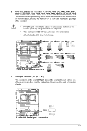
.... • These are not jumpers! DO NOT place jumper caps on the motherboard, ensuring that the black wire of each cable matches the ground pin of the connector. • DO NOT forget to connect the fan cables to ... a slot opening at the back of these connectors, then install the module to the fan connectors on the fan connectors! • All fans feature the ASUS Smart Fan technology. 7. Serial port connector (10-1 pin COM1) This connector is for the serial COM port. Connect the serial port module cable to one...
.... • These are not jumpers! DO NOT place jumper caps on the motherboard, ensuring that the black wire of each cable matches the ground pin of the connector. • DO NOT forget to connect the fan cables to ... a slot opening at the back of these connectors, then install the module to the fan connectors on the fan connectors! • All fans feature the ASUS Smart Fan technology. 7. Serial port connector (10-1 pin COM1) This connector is for the serial COM port. Connect the serial port module cable to one...

