Installation Guide
Page 3
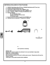
MATERIALS INCLUDED IN THIS PACKAGE: 1) VOH681A Video Monitor with out TV Tuner / VOH682A Video Monitor with TV Tuner (1 pc) 2) Accessory Harness (P/N 8010730) (1 pc) 3) 12 Pin Power / Signal harness (P/N 112B2821) (1 pc) 4) 2 Pin Power Wire Harness with choke (P/N 112B2824) (1 pc) 5) RCA "Y" Adapter (1 Male to 2 Female) (P/N 0892165) (1 pc) 6) Hardware Package #4 x 3/8" Screws (12 pcs) #8 x 5/8" Self Drilling Screws (4 pcs) #8 Washers...
MATERIALS INCLUDED IN THIS PACKAGE: 1) VOH681A Video Monitor with out TV Tuner / VOH682A Video Monitor with TV Tuner (1 pc) 2) Accessory Harness (P/N 8010730) (1 pc) 3) 12 Pin Power / Signal harness (P/N 112B2821) (1 pc) 4) 2 Pin Power Wire Harness with choke (P/N 112B2824) (1 pc) 5) RCA "Y" Adapter (1 Male to 2 Female) (P/N 0892165) (1 pc) 6) Hardware Package #4 x 3/8" Screws (12 pcs) #8 x 5/8" Self Drilling Screws (4 pcs) #8 Washers...

Installation Guide
Page 4
...on p6. System 2: Video Monitor with the VOH681A and VOH 682A series Drop Down Video Systems: System 1: Video Monitor without tuner (VOH681A), VCP. -All wiring necessary is intended to give a rough guideline of mounting. Refer to the wiring diagram on the video monitor itself . The hinging mechanism ...to a VOH681A system. Be sure that all areas where interconnecting wire harnesses will not be added to a VOH682A system using the speaker outputs. Refer to the wiring diagram on p7. -The VOH681A and VOH 682A video systems are only intended for horizontal, drop down installation. It...
...on p6. System 2: Video Monitor with the VOH681A and VOH 682A series Drop Down Video Systems: System 1: Video Monitor without tuner (VOH681A), VCP. -All wiring necessary is intended to give a rough guideline of mounting. Refer to the wiring diagram on the video monitor itself . The hinging mechanism ...to a VOH681A system. Be sure that all areas where interconnecting wire harnesses will not be added to a VOH682A system using the speaker outputs. Refer to the wiring diagram on p7. -The VOH681A and VOH 682A video systems are only intended for horizontal, drop down installation. It...

Installation Guide
Page 5
... B) The headliner may be trimmed to the "Mini-Console installation" section later in the acc. Refer to fit the contour of the video monitor and related console accessories. 3) Generally, the best location for cutting Figure 3 4 FULL SIZE CONSOLE INSTALLATION There are several additional features, and are...and location will vary from vehicle to be additional preparation work necessary, depending on the installation of the vehicle's headliner. Some of these wires can be used as per the drawing below C) If the mini-console (PN 1181300) will be used, it can remove the shelf...
... B) The headliner may be trimmed to the "Mini-Console installation" section later in the acc. Refer to fit the contour of the video monitor and related console accessories. 3) Generally, the best location for cutting Figure 3 4 FULL SIZE CONSOLE INSTALLATION There are several additional features, and are...and location will vary from vehicle to be additional preparation work necessary, depending on the installation of the vehicle's headliner. Some of these wires can be used as per the drawing below C) If the mini-console (PN 1181300) will be used, it can remove the shelf...

Installation Guide
Page 8
... the main PCB and into the Mini-Din Connector on the main PCB 4) Pull the wire tie loop tight and cut off the excess. 5) Connect the 12 pin harness to the mating connector on the Video Monitor. 6) Connect the wired RF Modulator and / or the remote headphone jacks to the video... monitor if those options are being included. 7) Connect power harness to Instructions with Non-Stereo Installations Item# 35b 1)...
... the main PCB and into the Mini-Din Connector on the main PCB 4) Pull the wire tie loop tight and cut off the excess. 5) Connect the 12 pin harness to the mating connector on the Video Monitor. 6) Connect the wired RF Modulator and / or the remote headphone jacks to the video... monitor if those options are being included. 7) Connect power harness to Instructions with Non-Stereo Installations Item# 35b 1)...

Installation Guide
Page 9
... other A/V Component can be routed as in steps 2 and 3 above. Note: Installation Guide covers models : VOH682A. -7- "Y" Adapter for use with the RF Right Input Modulator Kit for the 12 pin wiring harness. 2) Remove screws on PCB Cover. This second harness would plug into the Mini-Din Connector on the... on the face of the VCP. left Mini Din) 4= Aux Input (RCA jacks on the Video Monitor. 6) Connect the wired RF Modulator and / or the remote headphone jacks to the video monitor if those options are being included. 7) Connect power harness to the vehicle for further details. RCA-Female...
... other A/V Component can be routed as in steps 2 and 3 above. Note: Installation Guide covers models : VOH682A. -7- "Y" Adapter for use with the RF Right Input Modulator Kit for the 12 pin wiring harness. 2) Remove screws on PCB Cover. This second harness would plug into the Mini-Din Connector on the... on the face of the VCP. left Mini Din) 4= Aux Input (RCA jacks on the Video Monitor. 6) Connect the wired RF Modulator and / or the remote headphone jacks to the video monitor if those options are being included. 7) Connect power harness to the vehicle for further details. RCA-Female...

Installation Guide
Page 10
...the 1999 Dodge Caravan, may require that the purple / brown (Lamp auto) wire be connected to the door pin switch wire, as the additional current draw of the Monitor's lights may not be supported by the output of these wires will rest at ground. On a negative switched system, with all the doors ...closed and the lights out, both wires at the dome light will switch to ...
...the 1999 Dodge Caravan, may require that the purple / brown (Lamp auto) wire be connected to the door pin switch wire, as the additional current draw of the Monitor's lights may not be supported by the output of these wires will rest at ground. On a negative switched system, with all the doors ...closed and the lights out, both wires at the dome light will switch to ...

Installation Guide
Page 11
...sound is on. (Refer to the tuner. Negative Switched Dome lighting To 12 pin connector on p5 and p6. Static on Red wire at Video Monitor Remedy: -Verify +12 VDC on TV Stations (Tuner Version Only) -Press Auto Program button. Verify antenna mounting and connections to ...To constant +12vdc Troubleshooting: Symptom: No power at 2 pin Power Harness behind video monitor. Verify connections at 2 pin Power Harness Power but no video or sound -Verify that the IR LED ( p6 or p7 Wiring Diagram) is selected (i.e.: 1,2,3 or 4). If problem is limited to the dash radio...
...sound is on. (Refer to the tuner. Negative Switched Dome lighting To 12 pin connector on p5 and p6. Static on Red wire at Video Monitor Remedy: -Verify +12 VDC on TV Stations (Tuner Version Only) -Press Auto Program button. Verify antenna mounting and connections to ...To constant +12vdc Troubleshooting: Symptom: No power at 2 pin Power Harness behind video monitor. Verify connections at 2 pin Power Harness Power but no video or sound -Verify that the IR LED ( p6 or p7 Wiring Diagram) is selected (i.e.: 1,2,3 or 4). If problem is limited to the dash radio...