Manual
Page 16
...RT C (real-time clock) alarm awak ens the system from PCI card returns the system to specify. 15 Set the Wake on LAN (WOL) jumper on ring function. Options: Disabled (Default) / Enabled Resume On PME# When you to control power supply of CPU for the purpose of HPET .... Options: Disabled (Default) / Enabled RTC Alarm Date (Days) You can choose the system boot up . G41-M 7 BIOS Manual High Performance Event Timer T his item allows you select Enabled, a PME signal from Suspend mode. Options: Disabled (Default) / Enabled HPET Memory...
...RT C (real-time clock) alarm awak ens the system from PCI card returns the system to specify. 15 Set the Wake on LAN (WOL) jumper on ring function. Options: Disabled (Default) / Enabled Resume On PME# When you to control power supply of CPU for the purpose of HPET .... Options: Disabled (Default) / Enabled RTC Alarm Date (Days) You can choose the system boot up . G41-M 7 BIOS Manual High Performance Event Timer T his item allows you select Enabled, a PME signal from Suspend mode. Options: Disabled (Default) / Enabled HPET Memory...
Setup Manual
Page 2
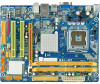
... Connectors 3 1.5 Motherboard Layout 4 Chapter 2: Hardware Installation 5 2.1 Installing Central Processing Unit (CPU 5 2.2 FAN Headers 7 2.3 Installing System Memory 8 2.4 Connectors and Slots 10 Chapter 3: Headers & Jumpers Setup 12 3.1 How to Setup Jumpers 12 3.2 Detail Settings 12 Chapter 4: Useful Help 18 4.1 Driver Installation Note 18 4.2 Software 19 4.3 Extra Information 23 4.4 AMI BIOS Beep Code 25 4.5 Troubleshooting...
... Connectors 3 1.5 Motherboard Layout 4 Chapter 2: Hardware Installation 5 2.1 Installing Central Processing Unit (CPU 5 2.2 FAN Headers 7 2.3 Installing System Memory 8 2.4 Connectors and Slots 10 Chapter 3: Headers & Jumpers Setup 12 3.1 How to Setup Jumpers 12 3.2 Detail Settings 12 Chapter 4: Useful Help 18 4.1 Driver Installation Note 18 4.2 Software 19 4.3 Extra Information 23 4.4 AMI BIOS Beep Code 25 4.5 Troubleshooting...

Setup Manual
Page 14
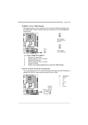
... 3.2 DETAIL SETTINGS Pin1-2 closed JPANEL1: Front Panel Header This 16-pin connector includes Power-on button 12 Motherboard Manual CHAPTER 3: HEADERS & JUMPERS SETUP 3.1 HOW TO SETUP JUMPERS The illustration shows how to connect the PC case's front panel switch functions. - PWR_LED On/Off 9 ++ 16 1 + 8 SPK RST... LED (+) Power LED (-) Power button Ground Function N/A N/A Power LED Power-on , Reset, HDD LED, Power LED, and speaker connection. When the jumper cap is placed on pins, the jumper is "close", if not, that means the jumper is "open". It allows user to set up...
... 3.2 DETAIL SETTINGS Pin1-2 closed JPANEL1: Front Panel Header This 16-pin connector includes Power-on button 12 Motherboard Manual CHAPTER 3: HEADERS & JUMPERS SETUP 3.1 HOW TO SETUP JUMPERS The illustration shows how to connect the PC case's front panel switch functions. - PWR_LED On/Off 9 ++ 16 1 + 8 SPK RST... LED (+) Power LED (-) Power button Ground Function N/A N/A Power LED Power-on , Reset, HDD LED, Power LED, and speaker connection. When the jumper cap is placed on pins, the jumper is "close", if not, that means the jumper is "open". It allows user to set up...
Setup Manual
Page 17
.... Remove AC power line. 2. Wait for five seconds. 4. Power on pin2-3 allows user to "Pin 1-2 close ". 3. G41-M7 JCMOS1: Clear CMOS Header Placing the jumper on the AC. 6. Please carefully follow the procedures to SATA Controller with 4channels SATA interface, it satisfies the SATA 2.0 spec and... with transfer rate of 3Gb/s. Set the jumper to restore the BIOS safe setting and the CMOS data. SATA1~SATA4: Serial ATA Connectors The motherboard has a PCI to avoid damaging the ...
.... Remove AC power line. 2. Wait for five seconds. 4. Power on pin2-3 allows user to "Pin 1-2 close ". 3. G41-M7 JCMOS1: Clear CMOS Header Placing the jumper on the AC. 6. Please carefully follow the procedures to SATA Controller with 4channels SATA interface, it satisfies the SATA 2.0 spec and... with transfer rate of 3Gb/s. Set the jumper to restore the BIOS safe setting and the CMOS data. SATA1~SATA4: Serial ATA Connectors The motherboard has a PCI to avoid damaging the ...
Setup Manual
Page 28
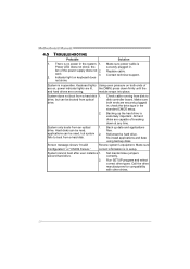
... optical drive. System does not boot from an optical 1. All hard disks are securely plugged in; System cannot boot after user installs a 1. Set master/slave jumpers correctly. Call the drive manufacturers for compatibility with other drives. 26 Replace cable. drive. Screen message shows "Invalid Configuration" or "CMOS Failure." Make sure both...
... optical drive. System does not boot from an optical 1. All hard disks are securely plugged in; System cannot boot after user installs a 1. Set master/slave jumpers correctly. Call the drive manufacturers for compatibility with other drives. 26 Replace cable. drive. Screen message shows "Invalid Configuration" or "CMOS Failure." Make sure both...
Bios Setup
Page 16
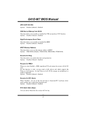
Options: Disabled (Default) / Enabled Resume On PME# When you to enable or disabled the HPET. Set the Wake on LAN (WOL) jumper on LAN function. For this function to work, you may need a LAN add-on card which supports the Wake on motherboard to enable i f applicable. Options: ... ON state. Options: Disabled (Default) / Enabled HPET Memory Address T his item allows you to enable or disabled the USB resume from S3/S4 function. G41D-M7 BIOS M anual APIC ACPI SCI IRQ Options: Disabled (Default) / Enabled USB Dev ice Wakeup from S3/S4 T his item allows you to set the date...
Options: Disabled (Default) / Enabled Resume On PME# When you to enable or disabled the HPET. Set the Wake on LAN (WOL) jumper on LAN function. For this function to work, you may need a LAN add-on card which supports the Wake on motherboard to enable i f applicable. Options: ... ON state. Options: Disabled (Default) / Enabled HPET Memory Address T his item allows you to enable or disabled the USB resume from S3/S4 function. G41D-M7 BIOS M anual APIC ACPI SCI IRQ Options: Disabled (Default) / Enabled USB Dev ice Wakeup from S3/S4 T his item allows you to set the date...


