
Setup Manual
Page 2
Table of Contents Chapter 1: Introduction 1 1.1 Before You Start 1 1.2 Package Checklist 1 1.3 Motherboard Features 2 1.4 Rear Panel Connectors 3 1.5 Motherboard Layout 4 Chapter 2: Hardware Installation 5 2.1 Installing Central Processing Unit (CPU 5 2.2 FAN Headers 7 2.3 Installing System Memory 8 2.4 Connectors and Slots 10 Chapter 3: Headers & Jumpers Setup 13 3.1 How to ...
Table of Contents Chapter 1: Introduction 1 1.1 Before You Start 1 1.2 Package Checklist 1 1.3 Motherboard Features 2 1.4 Rear Panel Connectors 3 1.5 Motherboard Layout 4 Chapter 2: Hardware Installation 5 2.1 Installing Central Processing Unit (CPU 5 2.2 FAN Headers 7 2.3 Installing System Memory 8 2.4 Connectors and Slots 10 Chapter 3: Headers & Jumpers Setup 13 3.1 How to ...
Setup Manual
Page 3
... (optional) Serial ATA Power Cable X 1 (optional) Note: The package contents may be different due to area or your motherboard version. 1 TH61MU3/H61MU3/H61MH/H61ML CHAPTER 1: INTRODUCTION 1.1 BEFORE YOU START Thank you take the motherboard out from anti-static bag, ground yourself properly by touching any unfastened small parts inside the case after installation...
... (optional) Serial ATA Power Cable X 1 (optional) Note: The package contents may be different due to area or your motherboard version. 1 TH61MU3/H61MU3/H61MH/H61ML CHAPTER 1: INTRODUCTION 1.1 BEFORE YOU START Thank you take the motherboard out from anti-static bag, ground yourself properly by touching any unfastened small parts inside the case after installation...
Setup Manual
Page 4
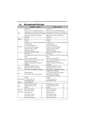
... Front Panel Connector x1 Front Panel Connector x1 Front Audio Connector x1 Front Audio Connector x1 S/PDIF out Connector x1 S/PDIF out Connector x1 2 Motherboard Manual 1.3 MOTHERBOARD FEATURES TH61MU3 / H61MU3 H61MH / H61ML Socket 1155 Socket 1155 Intel Core i7 / i5 / i3/ Pentium processor Intel Core i7 / i5 / i3/ Pentium processor Supports Execute Disable...
... Front Panel Connector x1 Front Panel Connector x1 Front Audio Connector x1 Front Audio Connector x1 S/PDIF out Connector x1 S/PDIF out Connector x1 2 Motherboard Manual 1.3 MOTHERBOARD FEATURES TH61MU3 / H61MU3 H61MH / H61ML Socket 1155 Socket 1155 Intel Core i7 / i5 / i3/ Pentium processor Intel Core i7 / i5 / i3/ Pentium processor Supports Execute Disable...
Setup Manual
Page 5
...VGA Port x1 DVI-D Port x1 LAN Port x1 USB2.0 Port x4 Audio Jack x3 200 (W) x 244 (L) mm Windows XP / Vista / 7 Biostar reserves the right to add or remove support for any OS with or without notice 1.4 REAR PANEL CONNECTORS PS /2 Keyboard / Mouse USB2.0X2 HDMI ...3 .0X 2 (For TH61MU3 & H61MU3) USB 2 .0X 2 (For H61MH & H61ML) NOTE: HDMI / DVI-D / VGA Output require an Intel Core family processor with Intel Graphics Technology. NOTE: Maximum resolution: HDMI: 1920 x 1200 @60Hz DVI: 1920 x 1200 @60Hz VGA: 2048 x 1536 @75Hz NOTE: This motherboard supports Multiple VGA output, and the ...
...VGA Port x1 DVI-D Port x1 LAN Port x1 USB2.0 Port x4 Audio Jack x3 200 (W) x 244 (L) mm Windows XP / Vista / 7 Biostar reserves the right to add or remove support for any OS with or without notice 1.4 REAR PANEL CONNECTORS PS /2 Keyboard / Mouse USB2.0X2 HDMI ...3 .0X 2 (For TH61MU3 & H61MU3) USB 2 .0X 2 (For H61MH & H61ML) NOTE: HDMI / DVI-D / VGA Output require an Intel Core family processor with Intel Graphics Technology. NOTE: Maximum resolution: HDMI: 1920 x 1200 @60Hz DVI: 1920 x 1200 @60Hz VGA: 2048 x 1536 @75Hz NOTE: This motherboard supports Multiple VGA output, and the ...

Setup Manual
Page 6
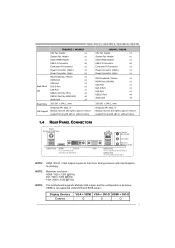
Motherboard Manual 1.5 MOTHERBOARD LAYOUT USBKB1 DDR3_B1 DDR3_A1 HDM I1 DVI1 Socket 1155 CPU1 CPU_FAN1 ATXPW R 1 VGA1 SATA1 SATA3 SATA2 SATA4 RJ45USB1 LAN AUDIO1 ATXPWR2 PEX16_1 PCI1 H61 BIOS PCI2 CODEC PEX1_1 Super I/O BAT1 J SPDIFOUT1 F_ AUDIO1 J_PRINT1 J_COM1 CIR1 F_USB1 F_USB2 JCMOS1 SYS_FAN1 PANEL1 Note: ■ represents the 1st pin. 4
Motherboard Manual 1.5 MOTHERBOARD LAYOUT USBKB1 DDR3_B1 DDR3_A1 HDM I1 DVI1 Socket 1155 CPU1 CPU_FAN1 ATXPW R 1 VGA1 SATA1 SATA3 SATA2 SATA4 RJ45USB1 LAN AUDIO1 ATXPWR2 PEX16_1 PCI1 H61 BIOS PCI2 CODEC PEX1_1 Super I/O BAT1 J SPDIFOUT1 F_ AUDIO1 J_PRINT1 J_COM1 CIR1 F_USB1 F_USB2 JCMOS1 SYS_FAN1 PANEL1 Note: ■ represents the 1st pin. 4

Setup Manual
Page 8
Step 5: Put the CPU Fan and heatsink assembly on the CPU and buckle it on CPU should point forwards this triangular cut edge. Step 4: Hold the CPU down firmly, and then lower the lever to locked position to complete the installation. 6 The CPU will fit only in the correct orientation. Connect the CPU FAN power cable into the CPU_FAN1 to complete the installation. Motherboard Manual Step 3: Look for the triangular cut edge on socket, and the golden dot on the retention frame.
Step 5: Put the CPU Fan and heatsink assembly on the CPU and buckle it on CPU should point forwards this triangular cut edge. Step 4: Hold the CPU down firmly, and then lower the lever to locked position to complete the installation. 6 The CPU will fit only in the correct orientation. Connect the CPU FAN power cable into the CPU_FAN1 to complete the installation. Motherboard Manual Step 3: Look for the triangular cut edge on socket, and the golden dot on the retention frame.

Setup Manual
Page 10
Unlock a DIMM slot by pressing the retaining clips outward. Insert the DIMM vertically and firmly into the slot until the retaining chip snap back in place and the DIMM is properly seated. 8 Motherboard Manual 2.3 INSTALLING SYSTEM MEMORY A. Align a DIMM on the slot such that the notch on the DIMM matches the break on the Slot. 2. DDR3 module DDR3_B1 DDR3_A1 1.
Unlock a DIMM slot by pressing the retaining clips outward. Insert the DIMM vertically and firmly into the slot until the retaining chip snap back in place and the DIMM is properly seated. 8 Motherboard Manual 2.3 INSTALLING SYSTEM MEMORY A. Align a DIMM on the slot such that the notch on the DIMM matches the break on the Slot. 2. DDR3 module DDR3_B1 DDR3_A1 1.

Setup Manual
Page 12
Pin Assignment 1 +12V 2 +12V 2 13 Ground 4 Ground 3 4 10 Motherboard Manual 2.4 CONNECTORS AND SLOTS SATA1~SATA4: Serial ATA Connectors The motherboard has a PCI to CPU power circuit. SATA1 SATA3 SATA2 SATA4 7 4 1 Pin Assignment 1 Ground 2 TX+ 3 TX4 Ground 5 RX6 RX+ 7 Ground ATXPWR2: ATX Power Source Connector This connector provides +12V to SATA Controller with 4channels SATA interface, it satisfies the SATA 2.0 spec and with transfer rate of 3Gb/s.
Pin Assignment 1 +12V 2 +12V 2 13 Ground 4 Ground 3 4 10 Motherboard Manual 2.4 CONNECTORS AND SLOTS SATA1~SATA4: Serial ATA Connectors The motherboard has a PCI to CPU power circuit. SATA1 SATA3 SATA2 SATA4 7 4 1 Pin Assignment 1 Ground 2 TX+ 3 TX4 Ground 5 RX6 RX+ 7 Ground ATXPWR2: ATX Power Source Connector This connector provides +12V to SATA Controller with 4channels SATA interface, it satisfies the SATA 2.0 spec and with transfer rate of 3Gb/s.

Setup Manual
Page 14
Maximum theoretical realized bandwidth of 16GB/s totally. - PCI-Express supports a raw bit-rate of 5.0Gb/s on the data pins. Motherboard Manual PCI1/PCI2: Peripheral Component Interconnect Slots This motherboard is designated as 32 bits. PCI-Express 2.0 compliant. - PEX1_1: PCI-Express Gen2 x1 Slot - PCI-Express 1.1 compliant. - PEX16_1 PEX1_1 12 P CI 1 PCI2 PEX16_1: PCI...
Maximum theoretical realized bandwidth of 16GB/s totally. - PCI-Express supports a raw bit-rate of 5.0Gb/s on the data pins. Motherboard Manual PCI1/PCI2: Peripheral Component Interconnect Slots This motherboard is designated as 32 bits. PCI-Express 2.0 compliant. - PEX1_1: PCI-Express Gen2 x1 Slot - PCI-Express 1.1 compliant. - PEX16_1 PEX1_1 12 P CI 1 PCI2 PEX16_1: PCI...
Setup Manual
Page 16
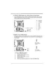
... Placing the jumper on pin2-3 allows user to connect additional USB cable on the AC. 6. Wait for USB 2.0 Ports at Front Panel This motherboard provides 2 USB 2.0 headers, which allows user to restore the BIOS safe setting and the CMOS data. Remove AC power line. 2. Set the... jumper to avoid damaging the motherboard. 3 1 Pin 1-2 Close: Normal Operation (Default). 3 1 3 Pin 2-3 Close: 1 Clear CMOS data. ※ Clear CMOS Procedures: 1. Power on the PC front panel, ...
... Placing the jumper on pin2-3 allows user to connect additional USB cable on the AC. 6. Wait for USB 2.0 Ports at Front Panel This motherboard provides 2 USB 2.0 headers, which allows user to restore the BIOS safe setting and the CMOS data. Remove AC power line. 2. Set the... jumper to avoid damaging the motherboard. 3 1 Pin 1-2 Close: Normal Operation (Default). 3 1 3 Pin 2-3 Close: 1 Clear CMOS data. ※ Clear CMOS Procedures: 1. Power on the PC front panel, ...

Setup Manual
Page 17
TH61MU3/H61MU3/H61MH/H61ML F_AUDIO1: Front Panel Audio Header This header allows user to send 9 Ring indicator 10 NC 1 9 15 Pin Assignment 1 Carrier detect 2 Received data 3 Transmitted ... Audio-out Connector This connector allows user to connect the PCI bracket SPDIF output header. 1 3 Pin Assignment 1 +5V 2 SPDIF_OUT 3 Ground J_COM1: Serial port Connector The motherboard has a Serial Port Connector for connecting RS-232 Port.
TH61MU3/H61MU3/H61MH/H61ML F_AUDIO1: Front Panel Audio Header This header allows user to send 9 Ring indicator 10 NC 1 9 15 Pin Assignment 1 Carrier detect 2 Received data 3 Transmitted ... Audio-out Connector This connector allows user to connect the PCI bracket SPDIF output header. 1 3 Pin Assignment 1 +5V 2 SPDIF_OUT 3 Ground J_COM1: Serial port Connector The motherboard has a Serial Port Connector for connecting RS-232 Port.

Setup Manual
Page 18
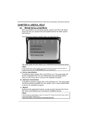
Motherboard Manual J_PRINT1: Printer Port Connector This header allows you to connector printer on the PC. 2 26 Pin Assignment 1 -Strobe 2 -ALF 3 Data 0 4 -Error 5 Data 1 6 -Init 7 Data 2 8 -...
Motherboard Manual J_PRINT1: Printer Port Connector This header allows you to connector printer on the PC. 2 26 Pin Assignment 1 -Strobe 2 -ALF 3 Data 0 4 -Error 5 Data 1 6 -Init 7 Data 2 8 -...
Setup Manual
Page 19
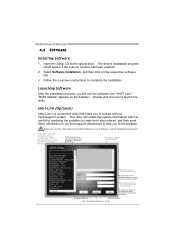
... following window after you insert the Driver CD, please use file browser to locate and execute the file SETUP.EXE under your motherboard and operating system. Click on each software title to launch the installation program. A. Click on the Manual icon to browse for your...Note: If this window didn't show up after you insert the CD The setup guide will list the compatible driver for available manual. C. TH61MU3/H61MU3/H61MH/H61ML CHAPTER 4: USEFUL HELP 4.1 DRIVER INSTALLATION NOTE After you installed your operating system, please insert the Fully Setup Driver CD into your optical...
... following window after you insert the Driver CD, please use file browser to locate and execute the file SETUP.EXE under your motherboard and operating system. Click on each software title to launch the installation program. A. Click on the Manual icon to browse for your...Note: If this window didn't show up after you insert the CD The setup guide will list the compatible driver for available manual. C. TH61MU3/H61MU3/H61MH/H61ML CHAPTER 4: USEFUL HELP 4.1 DRIVER INSTALLATION NOTE After you installed your operating system, please insert the Fully Setup Driver CD into your optical...
Setup Manual
Page 20
... or the area cl ose to you use this information, you may not be collected in forma tion to contact with our Tech-Support system. Motherboard Manual 4.2 SOFTWARE Installing Software 1. Insert the Setup CD to launch the utility. Before you . Exi t thi s dialog. This utility will collect the system information which...
... or the area cl ose to you use this information, you may not be collected in forma tion to contact with our Tech-Support system. Motherboard Manual 4.2 SOFTWARE Installing Software 1. Insert the Setup CD to launch the utility. Before you . Exi t thi s dialog. This utility will collect the system information which...

Setup Manual
Page 21
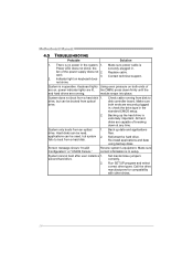
...a .txt file, click "Save As..." Your system information will see your system information including motherboard/BIOS/CPU/video/ device/OS information. If you are not using Outlook Express as your default... you may need to save this information, click "Send" to the following web http://www.biostar.com.tw/app/en-us/about/contact.php for your system information while using eHot-Line service...customer's data with other third parties, so please feel free to provide your confirmation; TH61MU3/H61MU3/H61MH/H61ML After filling up this information to cancel. A warning dialog would appear asking ...
...a .txt file, click "Save As..." Your system information will see your system information including motherboard/BIOS/CPU/video/ device/OS information. If you are not using Outlook Express as your default... you may need to save this information, click "Send" to the following web http://www.biostar.com.tw/app/en-us/about/contact.php for your system information while using eHot-Line service...customer's data with other third parties, so please feel free to provide your confirmation; TH61MU3/H61MU3/H61MH/H61ML After filling up this information to cancel. A warning dialog would appear asking ...

Setup Manual
Page 22
AWARD BIOS Show current BIOS information AMI BIOS Clear CMOS function (Only for AWARD BIOS) Save current BIOS to save file and enter file name. (We recommend that the file name should be English/number and no longer than 7 characters.) Then click Save. 20 Choose the position to a .bin file Update BIOS with a BIOS file Once click on this button, the saving dialog will show. Motherboard Manual BIOS Update BIOS Update is a convenient utility which allows you to update your motherboard BIOS under Windows system.
AWARD BIOS Show current BIOS information AMI BIOS Clear CMOS function (Only for AWARD BIOS) Save current BIOS to save file and enter file name. (We recommend that the file name should be English/number and no longer than 7 characters.) Then click Save. 20 Choose the position to a .bin file Update BIOS with a BIOS file Once click on this button, the saving dialog will show. Motherboard Manual BIOS Update BIOS Update is a convenient utility which allows you to update your motherboard BIOS under Windows system.

Setup Manual
Page 24
...follow steps below to avoid a damage of the CPU, and the system may not power on again. Power on the system again. 22 Motherboard Manual 4.3 EXTRA INFORMATION CPU Overheated If the system shuts down automatically after system is powered on for seconds. 3. The CPU cooler surface is... placed evenly with the CPU speed. CPU fan is over heated, the motherboard will shutdown automatically to relief the CPU protection function. 1. Wait for seconds. 2. When the CPU is rotated normally. 3. Remove the power ...
...follow steps below to avoid a damage of the CPU, and the system may not power on again. Power on the system again. 22 Motherboard Manual 4.3 EXTRA INFORMATION CPU Overheated If the system shuts down automatically after system is powered on for seconds. 3. The CPU cooler surface is... placed evenly with the CPU speed. CPU fan is over heated, the motherboard will shutdown automatically to relief the CPU protection function. 1. Wait for seconds. 2. When the CPU is rotated normally. 3. Remove the power ...

Setup Manual
Page 25
...add-in card. If the system video adapter is an add-in card, replace or 8 reseat the video adapter. Before declaring the motherboard beyond all other expansion 6, 7 cards are absent, consult your system manufacturer. Insert the cards back into the system one of Beeps... 3 Reseat the memory, or replace with the system. Consult your system manufacturer's technical support. This will reveal the malfunctioning card. TH61MU3/H61MU3/H61MH/H61ML 4.4 AMI BIOS BEEP CODE Boot Block Beep Codes Number of Beeps Description 1 No media present. (Insert diskette in floppy drive...
...add-in card. If the system video adapter is an add-in card, replace or 8 reseat the video adapter. Before declaring the motherboard beyond all other expansion 6, 7 cards are absent, consult your system manufacturer. Insert the cards back into the system one of Beeps... 3 Reseat the memory, or replace with the system. Consult your system manufacturer's technical support. This will reveal the malfunctioning card. TH61MU3/H61MU3/H61MH/H61ML 4.4 AMI BIOS BEEP CODE Boot Block Beep Codes Number of Beeps Description 1 No media present. (Insert diskette in floppy drive...
Setup Manual
Page 26
... lights are lit, the DIMM, press down at any time. All hard disks are securely plugged in; Make sure correct information is no power in . Motherboard Manual 4.5 TROUBLESHOOTING Probable Solution 1. Make sure power cable is inoperative. Indicator light on both ends are capable of the power supply does not 2. Keyboard lights...
... lights are lit, the DIMM, press down at any time. All hard disks are securely plugged in; Make sure correct information is no power in . Motherboard Manual 4.5 TROUBLESHOOTING Probable Solution 1. Make sure power cable is inoperative. Indicator light on both ends are capable of the power supply does not 2. Keyboard lights...
Bios Setup
Page 2
... supported. 1 DRAM S upport DDR3 SDRAM (Double Data Rate III Synchronous DRAM) is to describe the s ettings in the AMI UEFI BIOS Setup program on this motherboard. The Setup program allows users to modify the basic system configuration and save these settings to NVRAM. EPA Green PC Support T his AMI UEFI BIOS...
... supported. 1 DRAM S upport DDR3 SDRAM (Double Data Rate III Synchronous DRAM) is to describe the s ettings in the AMI UEFI BIOS Setup program on this motherboard. The Setup program allows users to modify the basic system configuration and save these settings to NVRAM. EPA Green PC Support T his AMI UEFI BIOS...

