
K8NHA M user's manual
Page 5
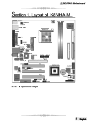
BIOSTAR Motherboard Section 1. Layout of K8NHA-M JKBMS1 1 JKBMSV1 1 JUSBV1 J1394_USB1 JCOM1 JCFAN1 1 DDR1 Socket 754 CPU1 Super I/O IT 8712F FDD1 1 JCOM3 JCOM2 JATXPWR2 JUSBLAN1 J1394A1 JSFAN2 1J U S B V 2 JAUDIO 1 JSPDIF_OUT 1 BIOS RTL8201BL 1 1 JAUDIO1 1 JSPDIF_IN 1 JCDIN2 JSATA3 1 PCI1 JSATA2 1 NVIDIA CK 8 CODEC 1 JCDIN1 VIA VT 6307 11 JWOL1 JDJ1 PCI2 CNR1 PCI3 1 1 JUSBV3 1 JUSB1 1 J3 JUSB2 IDE2 IDE1 1 JGAME1 BAT1 15 SATA Bridge 1 JSATA1 JSFAN1 JCMOS1 1 JCI1 1 1 2 JPANEL1 24 1 23 NOTE: " " represents the first pin. 5 English
BIOSTAR Motherboard Section 1. Layout of K8NHA-M JKBMS1 1 JKBMSV1 1 JUSBV1 J1394_USB1 JCOM1 JCFAN1 1 DDR1 Socket 754 CPU1 Super I/O IT 8712F FDD1 1 JCOM3 JCOM2 JATXPWR2 JUSBLAN1 J1394A1 JSFAN2 1J U S B V 2 JAUDIO 1 JSPDIF_OUT 1 BIOS RTL8201BL 1 1 JAUDIO1 1 JSPDIF_IN 1 JCDIN2 JSATA3 1 PCI1 JSATA2 1 NVIDIA CK 8 CODEC 1 JCDIN1 VIA VT 6307 11 JWOL1 JDJ1 PCI2 CNR1 PCI3 1 1 JUSBV3 1 JUSB1 1 J3 JUSB2 IDE2 IDE1 1 JGAME1 BAT1 15 SATA Bridge 1 JSATA1 JSFAN1 JCMOS1 1 JCI1 1 1 2 JPANEL1 24 1 23 NOTE: " " represents the first pin. 5 English
K8NHA M user's manual
Page 6
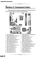
B C A F1 Socket 754 CPU1 Super I/O IT 8712F E D F E1 D1 GH C1 O 1 J K N N CODEC P Q RTL8201BL L M R VIA VT 6307 S TU V NVIDIA CK 8 B1 BAT1 SATA Bridge A1 ZY X W A Back Panel Connectors (p. 18) B JKBMSV1: 5V/5VSB Selection for Keyboard/Mouse (p. 16) C JUSBV1: 5V/5VSB Selection for J1394_USB1 (p. 14) D JCOM3: COM3 Header (p. ... Index This section helps you to locate the components in the motherboard and to find the details about them easily according to the mentioned pages. BIOSTAR Motherboard Section 2.
B C A F1 Socket 754 CPU1 Super I/O IT 8712F E D F E1 D1 GH C1 O 1 J K N N CODEC P Q RTL8201BL L M R VIA VT 6307 S TU V NVIDIA CK 8 B1 BAT1 SATA Bridge A1 ZY X W A Back Panel Connectors (p. 18) B JKBMSV1: 5V/5VSB Selection for Keyboard/Mouse (p. 16) C JUSBV1: 5V/5VSB Selection for J1394_USB1 (p. 14) D JCOM3: COM3 Header (p. ... Index This section helps you to locate the components in the motherboard and to find the details about them easily according to the mentioned pages. BIOSTAR Motherboard Section 2.
K8NHA M user's manual
Page 8
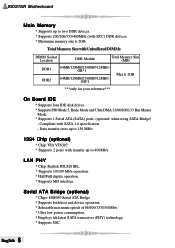
...MB) DDR1 DDR2 64MB/128MB/256MB/512MB/1GB*1 64MB/128MB/256MB/512MB/1GB*1 Max is 2GB. BIOSTAR Motherboard Main Memory * Supports up to two DDR devices. * Supports 200/266/333/400MHz (with SATA 1.0 specification - Compliant with ECC) DDR devices. * Maximum memory size is 2GB ***only for ... IDE disk drives. * Supports PIO Mode 5, Bride Mode and Ultra DMA 33/66/100/133 Bus Master Mode. * Supports 1 Serial ATA (SATA) ports. (optional: when using SATA Bridge) - English 8 Data transfer rates up to 150 MB/s 1394 Chip (optional) * Chip: VIA VT6307. * Supports 2 ports with transfer...
...MB) DDR1 DDR2 64MB/128MB/256MB/512MB/1GB*1 64MB/128MB/256MB/512MB/1GB*1 Max is 2GB. BIOSTAR Motherboard Main Memory * Supports up to two DDR devices. * Supports 200/266/333/400MHz (with SATA 1.0 specification - Compliant with ECC) DDR devices. * Maximum memory size is 2GB ***only for ... IDE disk drives. * Supports PIO Mode 5, Bride Mode and Ultra DMA 33/66/100/133 Bus Master Mode. * Supports 1 Serial ATA (SATA) ports. (optional: when using SATA Bridge) - English 8 Data transfer rates up to 150 MB/s 1394 Chip (optional) * Chip: VIA VT6307. * Supports 2 ports with transfer...

K8NHA M user's manual
Page 13
... with 2 channels STAT interface. An AGP card will attach directly to clear the Real Time Clock (RTC) Ram in CMOS. It satisfies the SATA 1.0 spec and can erase the CMOS RTC Ram data to four hard disk drives. Power on the AC. 6. PCI stands for Peripheral Component ... and a slave drive, so you to that provides PIO Mode 0~4, Bus Master, and Ultra DMA 33/ 66/ 100/ 133 functionality. Remove AC power line. 2. BIOSTAR Motherboard (2) Hard Disk Connectors: IDE1/ IDE2 The motherboard has a 32-bit Enhanced PCI IDE Controller that video card. It has two HDD connectors IDE1 (primary...
... with 2 channels STAT interface. An AGP card will attach directly to clear the Real Time Clock (RTC) Ram in CMOS. It satisfies the SATA 1.0 spec and can erase the CMOS RTC Ram data to four hard disk drives. Power on the AC. 6. PCI stands for Peripheral Component ... and a slave drive, so you to that provides PIO Mode 0~4, Bus Master, and Ultra DMA 33/ 66/ 100/ 133 functionality. Remove AC power line. 2. BIOSTAR Motherboard (2) Hard Disk Connectors: IDE1/ IDE2 The motherboard has a 32-bit Enhanced PCI IDE Controller that video card. It has two HDD connectors IDE1 (primary...