

M6TSU user's manual
Page 3
... 1-2 1.1 Features 1-2 1.1.1 Hardware 1-2 1.1.2 BIOS 1-6 1.1.3 Software 1-6 1.1.4 Accessories 1-6 1.2 Motherboard Installation 1-7 1.2.1 System Block Diagram 1-7 1.2.2 Layout of Motherboard 1-8 1.2.3 Quick Reference 1-9 1.3 CPU Installation 1-10 1.3.1 CPU Installation Procedure: Socket 370 1-10 1.3.2 CPU Fan Header: JCFAN1 1-11 1.3.3 System Fan Header: JSFAN2 1-11 1.4 RAM Module Installation 1-12 1.4.1 ...
... 1-2 1.1 Features 1-2 1.1.1 Hardware 1-2 1.1.2 BIOS 1-6 1.1.3 Software 1-6 1.1.4 Accessories 1-6 1.2 Motherboard Installation 1-7 1.2.1 System Block Diagram 1-7 1.2.2 Layout of Motherboard 1-8 1.2.3 Quick Reference 1-9 1.3 CPU Installation 1-10 1.3.1 CPU Installation Procedure: Socket 370 1-10 1.3.2 CPU Fan Header: JCFAN1 1-11 1.3.3 System Fan Header: JSFAN2 1-11 1.4 RAM Module Installation 1-12 1.4.1 ...

M6TSU user's manual
Page 7
M6TSU Highlights: 8 Contains on board I/O facilities, which brings to you with industry software and hardware standards. Chapter1 Motherboard Description Introduction System Overview Congratulations on board IDE facilities for full compliance and compatibility with the ultimate solution in data processing. This motherboard... is designed to take advantage of your new system! In the tradition of its predecessors, this motherboard continues a commitment to provide you the latest technology in ...
M6TSU Highlights: 8 Contains on board I/O facilities, which brings to you with industry software and hardware standards. Chapter1 Motherboard Description Introduction System Overview Congratulations on board IDE facilities for full compliance and compatibility with the ultimate solution in data processing. This motherboard... is designed to take advantage of your new system! In the tradition of its predecessors, this motherboard continues a commitment to provide you the latest technology in ...

M6TSU user's manual
Page 8
...; Power down timer from 533 MHz to 2 double sided or 3 single sided DIMMs at 66 MHz,100 MHz and 133MHz Front Side Bus frequency. Chapter1 Motherboard Description 1 Motherboard Description 1.1 Features 1.1.1 Hardware CPU − The Pentium®!!!
...; Power down timer from 533 MHz to 2 double sided or 3 single sided DIMMs at 66 MHz,100 MHz and 133MHz Front Side Bus frequency. Chapter1 Motherboard Description 1 Motherboard Description 1.1 Features 1.1.1 Hardware CPU − The Pentium®!!!
M6TSU user's manual
Page 9
Chapter1 Motherboard Description − Wakes up by BIOS. AC'97 Sound Codec Onboard − AC-LINK protocol compliance. − AC'97 2.1 compliant. − Single chip audio CODEC ...
Chapter1 Motherboard Description − Wakes up by BIOS. AC'97 Sound Codec Onboard − AC-LINK protocol compliance. − AC'97 2.1 compliant. − Single chip audio CODEC ...

M6TSU user's manual
Page 10
...(ATA port accessible during DMA transfer) 1-4 Supports 360KB, 720KB, 1.2MB, 1.44MB, and 2.88MB floppy disk drives. − Enhanced Digital Data Separator. − Serial Ports. Chapter1 Motherboard Description − MPU-401 MDI Support. − Intelligent Auto Power Management. − 2.88MB Super I/O Floppy Disk Controller. − Floppy Disk Available on -board IDE) −...
...(ATA port accessible during DMA transfer) 1-4 Supports 360KB, 720KB, 1.2MB, 1.44MB, and 2.88MB floppy disk drives. − Enhanced Digital Data Separator. − Serial Ports. Chapter1 Motherboard Description − MPU-401 MDI Support. − Intelligent Auto Power Management. − 2.88MB Super I/O Floppy Disk Controller. − Floppy Disk Available on -board IDE) −...
M6TSU user's manual
Page 11
.... − Fan speed sensors. System Speed Selection − Front side bus frequency may located front panel. Dimension (ATX form-factor) − 20cm X 30.5 cm (W x L) 1-5 Chapter1 Motherboard Description − Total ATA bus tri-state by the BIOS. Universal Serial Bus − Supports two Universal Serial Bus (USB) Ports. − Supports 48MHz USB...
.... − Fan speed sensors. System Speed Selection − Front side bus frequency may located front panel. Dimension (ATX form-factor) − 20cm X 30.5 cm (W x L) 1-5 Chapter1 Motherboard Description − Total ATA bus tri-state by the BIOS. Universal Serial Bus − Supports two Universal Serial Bus (USB) Ports. − Supports 48MHz USB...
M6TSU user's manual
Page 12
Chapter1 Motherboard Description 1.1.2 BIOS − AWARD BIOS. − ACPI Supported. − Supports APM1.2. − Setting the CPU Host and Memory clock frequency/Ratio. 1.1.3 Software Operating Systems − Offers the highest performance for MS-DOS, Windows NT, Windows 2000, Windows 9x, Windows ME, Windows XP, Novell, LINUX(Red Hat 7.0), UNIX, SCO UNIX etc. 1.1.4 Accessories − HDD Cable. − FDD Cable. − Rear I/O Panel for ATX Case (Optional). − CD for sound, VGA, IDE drivers and modem driver utilities. − Front USB cable (Optional). 1-6
Chapter1 Motherboard Description 1.1.2 BIOS − AWARD BIOS. − ACPI Supported. − Supports APM1.2. − Setting the CPU Host and Memory clock frequency/Ratio. 1.1.3 Software Operating Systems − Offers the highest performance for MS-DOS, Windows NT, Windows 2000, Windows 9x, Windows ME, Windows XP, Novell, LINUX(Red Hat 7.0), UNIX, SCO UNIX etc. 1.1.4 Accessories − HDD Cable. − FDD Cable. − Rear I/O Panel for ATX Case (Optional). − CD for sound, VGA, IDE drivers and modem driver utilities. − Front USB cable (Optional). 1-6

M6TSU user's manual
Page 13
Chapter1 Motherboard Description 1.2 Motherboard Installation 1.2.1 System Block Diagram VRM 370-Pin Socket Processor Clock DATA DATA CTRL CTRL ADDR ADDR Intel 82815EP B-Step 3 DIMM Modules UltraDMA/33/66/100 ... 4 PCI CONN 3 CNR AC'97 Link PCI CONN 2 LPC Bus SIO PCI CONN 1 UltraDMA/33/66/100 & RAID0/1/0+1 HIGH POINT HTP370 IDE Primary IDE Secondary M6TSU ATX(FSB: 133/100MHz) SUPPORTS 3 DIMMS SUPPORTS 1 AGP SLOT SUPPORTS 6 PCI SLOTS SUPPORTS 1 CNR SLOT SUPPORTS TELEPHONY FirmWare Hub Keyboard Mouse Floppy Parallel Game Port...
Chapter1 Motherboard Description 1.2 Motherboard Installation 1.2.1 System Block Diagram VRM 370-Pin Socket Processor Clock DATA DATA CTRL CTRL ADDR ADDR Intel 82815EP B-Step 3 DIMM Modules UltraDMA/33/66/100 ... 4 PCI CONN 3 CNR AC'97 Link PCI CONN 2 LPC Bus SIO PCI CONN 1 UltraDMA/33/66/100 & RAID0/1/0+1 HIGH POINT HTP370 IDE Primary IDE Secondary M6TSU ATX(FSB: 133/100MHz) SUPPORTS 3 DIMMS SUPPORTS 1 AGP SLOT SUPPORTS 6 PCI SLOTS SUPPORTS 1 CNR SLOT SUPPORTS TELEPHONY FirmWare Hub Keyboard Mouse Floppy Parallel Game Port...

M6TSU user's manual
Page 14
PRIMARY IDE CONN. Chapter1 Motherboard Description 1.2.2 Layout of Motherboard Model No.M6TSU JKBMS1 K/B & Mouse JUSB1 USB JCOM1 JCFAN1 1 JPRNT1 U41 SOCKET 370 COM1 Parallel Port Winbond I/O CPU1 U43 COM2 JCOM2 JSPKR1 SP-OUT JLIN1 LINE-IN JMIC1 ...
PRIMARY IDE CONN. Chapter1 Motherboard Description 1.2.2 Layout of Motherboard Model No.M6TSU JKBMS1 K/B & Mouse JUSB1 USB JCOM1 JCFAN1 1 JPRNT1 U41 SOCKET 370 COM1 Parallel Port Winbond I/O CPU1 U43 COM2 JCOM2 JSPKR1 SP-OUT JLIN1 LINE-IN JMIC1 ...
M6TSU user's manual
Page 15
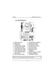
... Audio Header (JCDIN2) E. CNR Slot (CNR1) K. RAID Connector (*RAID1-2) O. ATX Power Connector (JATXPWR1) T. CD-ROM Audio Header (JCDIN1) G. Front USB Header (JUSB2) N. Chapter1 1.2.3 Quick Reference U A Motherboard Description T S R Q B P C D E O F G N H I . Clear CMOS Jumper (JCMOS1) P. Wake-On-LAN Header (JWOL1) J. Back Panel Connertors B. Front Audio Header (JAUDIO1) F. System FAN Header (JSFAN1) K L M L. DIMM Sockets (DIMM1...
... Audio Header (JCDIN2) E. CNR Slot (CNR1) K. RAID Connector (*RAID1-2) O. ATX Power Connector (JATXPWR1) T. CD-ROM Audio Header (JCDIN1) G. Front USB Header (JUSB2) N. Chapter1 1.2.3 Quick Reference U A Motherboard Description T S R Q B P C D E O F G N H I . Clear CMOS Jumper (JCMOS1) P. Wake-On-LAN Header (JWOL1) J. Back Panel Connertors B. Front Audio Header (JAUDIO1) F. System FAN Header (JSFAN1) K L M L. DIMM Sockets (DIMM1...
M6TSU user's manual
Page 16
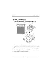
Press the lever down to a 90-degree angle. 2. Pull the lever sideways away from the socket then raise the lever up to complete the installation. 1-10 Match Pin A with the white dot/cut edge in the socket and look for the white dot or cut edge then insert the CPU. 3. Chapter1 Motherboard Description 1.3 CPU Installation 1.3.1 CPU Installation Procedure: Socket 370 Socket 370 1. Locate Pin A in the CPU.
Press the lever down to a 90-degree angle. 2. Pull the lever sideways away from the socket then raise the lever up to complete the installation. 1-10 Match Pin A with the white dot/cut edge in the socket and look for the white dot or cut edge then insert the CPU. 3. Chapter1 Motherboard Description 1.3 CPU Installation 1.3.1 CPU Installation Procedure: Socket 370 Socket 370 1. Locate Pin A in the CPU.

M6TSU user's manual
Page 17
Chapter1 1 JCFAN1 Motherboard Description 1 JSFAN1 1.3.2 CPU Fan Header: JCFAN1 Pin No. Assignment 1 Ground 2 +12v 3 FAN R.P.M. Signal input 1-11 Signal input 1.3.3 System Fan Header: JSFAN2 Pin No. 1 2 3 Assignment Ground +12v FAN R.P.M.
Chapter1 1 JCFAN1 Motherboard Description 1 JSFAN1 1.3.2 CPU Fan Header: JCFAN1 Pin No. Assignment 1 Ground 2 +12v 3 FAN R.P.M. Signal input 1-11 Signal input 1.3.3 System Fan Header: JSFAN2 Pin No. 1 2 3 Assignment Ground +12v FAN R.P.M.

M6TSU user's manual
Page 18
Chapter1 Motherboard Description 1.4 RAM Module Installation 1.4.1 DIMM DRAM Access Time: 3.3V Unbuffered SDRAM PC100/133 Type required. DRAM Type: 64MB/ 128MB/ 256MB/ 512MB DIMM Module (168pin) Total ...
Chapter1 Motherboard Description 1.4 RAM Module Installation 1.4.1 DIMM DRAM Access Time: 3.3V Unbuffered SDRAM PC100/133 Type required. DRAM Type: 64MB/ 128MB/ 256MB/ 512MB DIMM Module (168pin) Total ...
M6TSU user's manual
Page 19
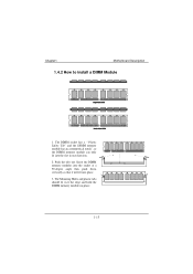
The Mounting Holes and plastic tabs should fit over the edge and hold the DIMM memory modules in one direction. 2. Push the tabs out. Insert the DIMM memory modules into the socket at a 90-degree angle then push down vertically so that it will fit into the slot in place. 1-13 The DIMM socket has a " Plastic Safety Tab" and the DIMM memory module has an asymmetrical notch", so the DIMM memory module can only fit into place. 3. Chapter1 Motherboard Description 1.4.2 How to install a DIMM Module 1.
The Mounting Holes and plastic tabs should fit over the edge and hold the DIMM memory modules in one direction. 2. Push the tabs out. Insert the DIMM memory modules into the socket at a 90-degree angle then push down vertically so that it will fit into the slot in place. 1-13 The DIMM socket has a " Plastic Safety Tab" and the DIMM memory module has an asymmetrical notch", so the DIMM memory module can only fit into place. 3. Chapter1 Motherboard Description 1.4.2 How to install a DIMM Module 1.

M6TSU user's manual
Page 20
Chapter1 Motherboard Description 1.5 Slots The slots in this motherboard are a means of the basic system. With these efficient facilities, you can increase the motherboard's capabilities by adding hardware that performs tasks that are not part of adding or enhancing the motherboard's features and capabilities. AGP Slot PCI Slots CNR Slot 1-14 Expansion slots are designed to hold expansion cards and connect them to the system bus.
Chapter1 Motherboard Description 1.5 Slots The slots in this motherboard are a means of the basic system. With these efficient facilities, you can increase the motherboard's capabilities by adding hardware that performs tasks that are not part of adding or enhancing the motherboard's features and capabilities. AGP Slot PCI Slots CNR Slot 1-14 Expansion slots are designed to hold expansion cards and connect them to the system bus.

M6TSU user's manual
Page 21
... This PCI slot is equipped with an Accelerated Graphics Port (AGP). Chapter1 Motherboard Description 1.5.1 AGP (Accelerated Graphics Port) Slot Unlike the mouse ports, keyboard ports and printer ports this motherboard does not have built in video facilities and therefore requires a video card ... defines a hardware scalable riser card interface, which supports audio, network and modem only. 1.5.3 PCI (Peripheral Component Interconnect) Slots This motherboard is designated as 32 bit. 1-15 PCI stands for Peripheral Component Interconnect and is a bus standard for expansion cards, which has,...
... This PCI slot is equipped with an Accelerated Graphics Port (AGP). Chapter1 Motherboard Description 1.5.1 AGP (Accelerated Graphics Port) Slot Unlike the mouse ports, keyboard ports and printer ports this motherboard does not have built in video facilities and therefore requires a video card ... defines a hardware scalable riser card interface, which supports audio, network and modem only. 1.5.3 PCI (Peripheral Component Interconnect) Slots This motherboard is designated as 32 bit. 1-15 PCI stands for Peripheral Component Interconnect and is a bus standard for expansion cards, which has,...
M6TSU user's manual
Page 22
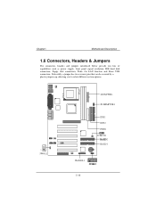
Chapter1 Motherboard Description 1.6 Connectors, Headers & Jumpers The connectors, headers and jumpers introduced below provide you to select different system options. 1 JWOL1 JATXPWR1 JDIMMPWR1 IDE1 IDE2 FDD1 1 JCMOS1 RAID2 RAID1 JPANEL1 1 JUSB2 1-16 Noticeably, a jumper has two or more pins that can be covered by a plastic jumper cap, allowing you lots of capabilities such as power supply, front panel signal revelation, IDE hard disk connection, floppy disk connection, Wake On LAN function and Front USB connection.
Chapter1 Motherboard Description 1.6 Connectors, Headers & Jumpers The connectors, headers and jumpers introduced below provide you to select different system options. 1 JWOL1 JATXPWR1 JDIMMPWR1 IDE1 IDE2 FDD1 1 JCMOS1 RAID2 RAID1 JPANEL1 1 JUSB2 1-16 Noticeably, a jumper has two or more pins that can be covered by a plastic jumper cap, allowing you lots of capabilities such as power supply, front panel signal revelation, IDE hard disk connection, floppy disk connection, Wake On LAN function and Front USB connection.
M6TSU user's manual
Page 23
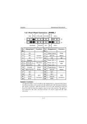
... information during the Power On Self-Test when the computer cannot use the video interface. The speaker is not connected to the motherboard at the front panel connector. Chapter1 Motherboard Description 1.6.1 Front Panel Connector: JPANEL1 K SLP NA POW-LED ON/OFF E (+) (+) (-) Y IRDA 2 24 1 23 SPEAKER (+) ...Function Sleep Button NA POWER LED Power-on Button IrDA Connector Speaker Connector An offboard speaker can be installed on the motherboard as a manufacturing option. An offboard speaker can be connected to the audio subsystem and does not receive output from the audio...
... information during the Power On Self-Test when the computer cannot use the video interface. The speaker is not connected to the motherboard at the front panel connector. Chapter1 Motherboard Description 1.6.1 Front Panel Connector: JPANEL1 K SLP NA POW-LED ON/OFF E (+) (+) (-) Y IRDA 2 24 1 23 SPEAKER (+) ...Function Sleep Button NA POWER LED Power-on Button IrDA Connector Speaker Connector An offboard speaker can be installed on the motherboard as a manufacturing option. An offboard speaker can be connected to the audio subsystem and does not receive output from the audio...
M6TSU user's manual
Page 24
Chapter1 Motherboard Description Reset Button This connector can be attached to a front panel power switch. HDD LED (Hard Disk LED Connector) This connector can be attached to ... Self Test). Power Button This connector can be attached to a momentary SPST switch. At least two seconds must be loaded. The LED will cause the motherboard to internal debounce circuitry on the front panel of a computer case. APM (Advanced Power Management) must pass before the power supply will recognize another on...
Chapter1 Motherboard Description Reset Button This connector can be attached to a front panel power switch. HDD LED (Hard Disk LED Connector) This connector can be attached to ... Self Test). Power Button This connector can be attached to a momentary SPST switch. At least two seconds must be loaded. The LED will cause the motherboard to internal debounce circuitry on the front panel of a computer case. APM (Advanced Power Management) must pass before the power supply will recognize another on...

M6TSU user's manual
Page 25
... supply, functions such as Modem Ring Wake-Up and Soft Power Off are supported on -board. Chapter1 Motherboard Description 1.6.2 ATX 20-pin Power Connector: JATXPWR1 This connector supports the power button on this motherboard. This power connector supports instant power-on functionality, which means that the system will boot up instantly when...
... supply, functions such as Modem Ring Wake-Up and Soft Power Off are supported on -board. Chapter1 Motherboard Description 1.6.2 ATX 20-pin Power Connector: JATXPWR1 This connector supports the power button on this motherboard. This power connector supports instant power-on functionality, which means that the system will boot up instantly when...

