
Setup Manual
Page 1
... reserves the right to revise this publication and to make c hanges to radio communications . D uplication of their respec tive companies . The content of this user's manual is not allowed without first obtaining the vendor's approval in this publication, in part or in whole, is subject to be c hanged without obligation to... here and s pecially disclaims any implied warranties of merchantability or fitness for any mis takes found to comply with the limits of the FCC Rules . MCP6P-M2 Setup Manual FCC Information and Copyright This equipment has been tes ted and found in writing.
... reserves the right to revise this publication and to make c hanges to radio communications . D uplication of their respec tive companies . The content of this user's manual is not allowed without first obtaining the vendor's approval in this publication, in part or in whole, is subject to be c hanged without obligation to... here and s pecially disclaims any implied warranties of merchantability or fitness for any mis takes found to comply with the limits of the FCC Rules . MCP6P-M2 Setup Manual FCC Information and Copyright This equipment has been tes ted and found in writing.

Setup Manual
Page 3
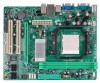
... ATA Powe r Cable X 1 (optional) USB 2.0 Cable X1 (optional) S/PDIF out Cable X 1 (optional) Note: The package contents may damage the equipment. MCP6P-M2 CHAPTER 1: INTRODUCTION 1.1 BEFORE YOU ST ART Thank you follow the instructions be fore ope ration. Before you take the mothe rboard out from anti-static... the mothe rboard, please make sure you for ATX Case X 1 Installation Guide X 1 Fully Se tup Drive r C D X 1 (full ve rsion manual files inside the case afte r installation. Keep the compute r from powe r outle t be low: „ Prepare a dry and stable work ing environment ...
... ATA Powe r Cable X 1 (optional) USB 2.0 Cable X1 (optional) S/PDIF out Cable X 1 (optional) Note: The package contents may damage the equipment. MCP6P-M2 CHAPTER 1: INTRODUCTION 1.1 BEFORE YOU ST ART Thank you follow the instructions be fore ope ration. Before you take the mothe rboard out from anti-static... the mothe rboard, please make sure you for ATX Case X 1 Installation Guide X 1 Fully Se tup Drive r C D X 1 (full ve rsion manual files inside the case afte r installation. Keep the compute r from powe r outle t be low: „ Prepare a dry and stable work ing environment ...
Setup Manual
Page 4
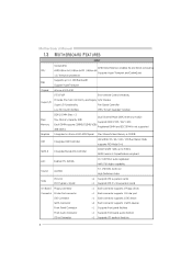
... SATA Conn ector Fron t Panel Connector Fron t Audio Conn ector CD-in itiatives, Super I/O Provides the most commonly u sed legacy H/W Mon itor Super I/O functionality . Motherboard Manual 1.3 MOT HERBOARD FEAT URES SPEC Socket AM2 AMD 64 Architectu re enables 32 and 64 bit compu ting Supports Hyper Tran sport and Cool= n =Quiet...
... SATA Conn ector Fron t Panel Connector Fron t Audio Conn ector CD-in itiatives, Super I/O Provides the most commonly u sed legacy H/W Mon itor Super I/O functionality . Motherboard Manual 1.3 MOT HERBOARD FEAT URES SPEC Socket AM2 AMD 64 Architectu re enables 32 and 64 bit compu ting Supports Hyper Tran sport and Cool= n =Quiet...

Setup Manual
Page 6
Motherboard Manual 1.5 JKBMS1 MOT HERBOARD LAYOUT JCFA N1 JATXP WR4 JKBM SPWR1 DIMMA1 J US BPWR1 JUSB1 JATXP WR1 JUSBLAN1 JUSBPW R2 IDE1 BIOS JA UDIO1 nForce 6100-430 JCDIN1 JA UDIOF 1 DIMMB1 J US B3 JUSB2 J US B4 J CMOS1 SATA 3 Super I/O JCOM1 Socket VGA A M2 L AN PCI-EX16 BAT1 PCI1 SATA4 Codec J SPDIF_O UT1 J PRNT1 PCI2 FDD1 SATA1 JSFAN1 SATA2 JPANEL1 Not e:
Motherboard Manual 1.5 JKBMS1 MOT HERBOARD LAYOUT JCFA N1 JATXP WR4 JKBM SPWR1 DIMMA1 J US BPWR1 JUSB1 JATXP WR1 JUSBLAN1 JUSBPW R2 IDE1 BIOS JA UDIO1 nForce 6100-430 JCDIN1 JA UDIOF 1 DIMMB1 J US B3 JUSB2 J US B4 J CMOS1 SATA 3 Super I/O JCOM1 Socket VGA A M2 L AN PCI-EX16 BAT1 PCI1 SATA4 Codec J SPDIF_O UT1 J PRNT1 PCI2 FDD1 SATA1 JSFAN1 SATA2 JPANEL1 Not e:

Setup Manual
Page 8
This completes the installation. 8 Motherboard Manual Step 4: Hold the CPU down firmly, and then close the lever toward direct B to the JCFAN1. Connect the CPU FAN power cable to complete the installation. Step 5: Put the CPU Fan on the CPU and buckle it.
This completes the installation. 8 Motherboard Manual Step 4: Hold the CPU down firmly, and then close the lever toward direct B to the JCFAN1. Connect the CPU FAN power cable to complete the installation. Step 5: Put the CPU Fan on the CPU and buckle it.

Setup Manual
Page 10
Insert the DIMM vertically and firmly into the slot until the retaining chip snap back in place and the DIMM is properly seated. 10 DIM MA1 DIM MB1 Memory Modules 1. Align a DIMM on the slot such that the notch on the DIMM matches the break on the Slot. 2. Unlock a DIMM slot by pressing the retaining clips outward. Motherboard Manual 2.3 INST ALLING SYST EM MEMORY A.
Insert the DIMM vertically and firmly into the slot until the retaining chip snap back in place and the DIMM is properly seated. 10 DIM MA1 DIM MB1 Memory Modules 1. Align a DIMM on the slot such that the notch on the DIMM matches the break on the Slot. 2. Unlock a DIMM slot by pressing the retaining clips outward. Motherboard Manual 2.3 INST ALLING SYST EM MEMORY A.
Setup Manual
Page 12
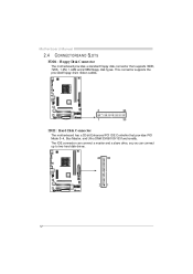
This connector supports the prov ided f loppy drive ribbon cables. FDD1: Floppy Disk Conne ctor 2 1 34 33 IDE1: Hard Disk Conne ctor The motherboard has a 32-bit Enhanced PCI IDE Controller that supports 360K, 720K, 1.2M, 1.44M and 2.88M floppy disk ty pes. The IDE connector can connect a master and a slave drive, so y ou can connect up to two hard disk driv es. 40 39 2 1 12 Motherboard Manual 2.4 CONNECT ORS AND SLOT S The motherboard prov ides a standard floppy disk connector that prov ides PIO Mode 0~4, Bus Master, and Ultra DMA 33/66/100/133 f unctionality.
This connector supports the prov ided f loppy drive ribbon cables. FDD1: Floppy Disk Conne ctor 2 1 34 33 IDE1: Hard Disk Conne ctor The motherboard has a 32-bit Enhanced PCI IDE Controller that supports 360K, 720K, 1.2M, 1.44M and 2.88M floppy disk ty pes. The IDE connector can connect a master and a slave drive, so y ou can connect up to two hard disk driv es. 40 39 2 1 12 Motherboard Manual 2.4 CONNECT ORS AND SLOT S The motherboard prov ides a standard floppy disk connector that prov ides PIO Mode 0~4, Bus Master, and Ultra DMA 33/66/100/133 f unctionality.
Setup Manual
Page 14
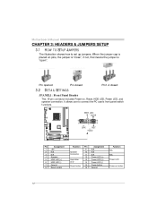
... LED (+) Power LED (-) Power button Ground Functio n N/A N/A Power LED Power-on pins, the jumper is "close", if not, that means the jumper is "open". Motherboard Manual CHAPTER 3: HEADERS & JUMPERS SETUP 3.1 HOW T O SET UP JUMPERS The illustration shows how to connect the PC case's front panel switch f unctions. Pin opened Pin closed...
... LED (+) Power LED (-) Power button Ground Functio n N/A N/A Power LED Power-on pins, the jumper is "close", if not, that means the jumper is "open". Motherboard Manual CHAPTER 3: HEADERS & JUMPERS SETUP 3.1 HOW T O SET UP JUMPERS The illustration shows how to connect the PC case's front panel switch f unctions. Pin opened Pin closed...
Setup Manual
Page 16
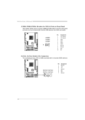
Motherboard Manual JUSB2/JUSB3/JUSB4: He ade rs for USB 2.0 Ports at Front Panel This header allows user to SATA Controller with internal USB devices, like USB card reader. SATA3 SATA4 SATA1 SATA2 1 4 7 Pin 1 2 3 4 5 6 7 Assignment Ground T X+ T XGround RXRX+ Ground 16 Pin Assignment +5V (fused) +5V (fused) USBUSBUSB+ USB+ Ground Ground Key NC JUSB3 JUSB2 JUSB4 2 1 10 9 1 2 3 4 5 6 7 8 9 10 SATA1~SATA4: Se rial ATA Connectors The motherboard has a PCI to connect additional USB cable on the PC f ront panel, and also can be connected with 4 channels SATA interf ace.
Motherboard Manual JUSB2/JUSB3/JUSB4: He ade rs for USB 2.0 Ports at Front Panel This header allows user to SATA Controller with internal USB devices, like USB card reader. SATA3 SATA4 SATA1 SATA2 1 4 7 Pin 1 2 3 4 5 6 7 Assignment Ground T X+ T XGround RXRX+ Ground 16 Pin Assignment +5V (fused) +5V (fused) USBUSBUSB+ USB+ Ground Ground Key NC JUSB3 JUSB2 JUSB4 2 1 10 9 1 2 3 4 5 6 7 8 9 10 SATA1~SATA4: Se rial ATA Connectors The motherboard has a PCI to connect additional USB cable on the PC f ront panel, and also can be connected with 4 channels SATA interf ace.

Setup Manual
Page 18
...: Normal Operation (default). 1 3 1 3 Pin 2-3 Close: Clear CMOS data. ※ Clear CMOS Proce dures: 1. 2. 3. 4. 5. 6. Set the jumper to connect the PCI bracket SPDIF output header. Motherboard Manual JSPDIF_O UT1: Digital Audio-out Conne ctor This connector allows user to "Pin 1-2 close ". Remov e AC power line. Wait f or f ive seconds. Power on pin2...
...: Normal Operation (default). 1 3 1 3 Pin 2-3 Close: Clear CMOS data. ※ Clear CMOS Proce dures: 1. 2. 3. 4. 5. 6. Set the jumper to connect the PCI bracket SPDIF output header. Motherboard Manual JSPDIF_O UT1: Digital Audio-out Conne ctor This connector allows user to "Pin 1-2 close ". Remov e AC power line. Wait f or f ive seconds. Power on pin2...

Setup Manual
Page 20
...: In order to support this func tion "Power-On s ys tem via keyboar d and mouse", "JKBMSPWR1" j umper cap s houl d be placed on Pi n 2-3. 20 Motherboard Manual JUSBPWR1/JUSBPWR2: Powe r Source Heade rs for USB Ports Pin 1-2 Close: JUSBPWR1: +5V for USB ports at f ront panel (JUSB2/JUSB3/JUSB4).
...: In order to support this func tion "Power-On s ys tem via keyboar d and mouse", "JKBMSPWR1" j umper cap s houl d be placed on Pi n 2-3. 20 Motherboard Manual JUSBPWR1/JUSBPWR2: Powe r Source Heade rs for USB Ports Pin 1-2 Close: JUSBPWR1: +5V for USB ports at f ront panel (JUSB2/JUSB3/JUSB4).

Setup Manual
Page 22
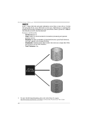
... high-availability solutions, or as a form of one driv e f ail, the controller switches to the other application that eliminates tedious manual backups to more expensive and less reliable media. Motherboard Manual RAID 1: Every read and write is 2. The mirrored (backup) copy of the data can be applied for the storage space of...
... high-availability solutions, or as a form of one driv e f ail, the controller switches to the other application that eliminates tedious manual backups to more expensive and less reliable media. Motherboard Manual RAID 1: Every read and write is 2. The mirrored (backup) copy of the data can be applied for the storage space of...
Setup Manual
Page 24
... block of good perf ormance, good f ault tolerance, and high capacity and storage efficiency. Write perf ormance can be CPU intensiv e. Fault Tolerance: Yes. Motherboard Manual RAID 5: RAID 5 stripes both data and parity information across all the drives in the array. Drawbacks: Individual block data transfer rate same as a single disk...
... block of good perf ormance, good f ault tolerance, and high capacity and storage efficiency. Write perf ormance can be CPU intensiv e. Fault Tolerance: Yes. Motherboard Manual RAID 5: RAID 5 stripes both data and parity information across all the drives in the array. Drawbacks: Individual block data transfer rate same as a single disk...

Setup Manual
Page 25
MCP6P-M2 CHAPTER 5: USEFUL HELP 5.1 DRIVER INST ALLAT ION NOT E After you ins ert the Driver CD, please use file brows er to locate and execute the file SETUP.EXE under your optical drive. A. Software Installation To install the software, please click on the Driver icon. Click on the Manual...this window didn't show up after you insert the CD The setup guide will need Acrobat R eader to launch the installation program. B. Manual Aside from http://www.adobe.com/products/acrobat/readstep 2.html 25 Driver Installation To install the driver, please click on the Software icon. ...
MCP6P-M2 CHAPTER 5: USEFUL HELP 5.1 DRIVER INST ALLAT ION NOT E After you ins ert the Driver CD, please use file brows er to locate and execute the file SETUP.EXE under your optical drive. A. Software Installation To install the software, please click on the Driver icon. Click on the Manual...this window didn't show up after you insert the CD The setup guide will need Acrobat R eader to launch the installation program. B. Manual Aside from http://www.adobe.com/products/acrobat/readstep 2.html 25 Driver Installation To install the driver, please click on the Software icon. ...
Setup Manual
Page 26
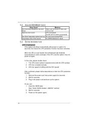
... after power on system for seconds. 3. Power on the system again. Clear the CMOS data. (See "Close CMOS Header: JCMOS1" section) 2. Or you can: 1. Motherboard Manual 5.2 AWARD BIOS BEEP CODE Meaning Video card not found or v ideo card memory bad CPU overheated System will shutdown automatically to relief the CPU protection...
... after power on system for seconds. 3. Power on the system again. Clear the CMOS data. (See "Close CMOS Header: JCMOS1" section) 2. Or you can: 1. Motherboard Manual 5.2 AWARD BIOS BEEP CODE Meaning Video card not found or v ideo card memory bad CPU overheated System will shutdown automatically to relief the CPU protection...

