
Setup Manual
Page 3
...board. „ Do not leave any unfastened small parts inside the case after installation. CHAPTER 1: INTRODUCTION N68S3B 1.1 BEFORE YOU START Thank you take the motherboard out from dangerous area, such as heat source, humid air and water. 1.2 PACKAGE CHECKLIST IDE Cable ...motherboard, please make sure you follow the instructions below: „ Prepare a dry and stable working environment with sufficient lighting. „ Always disconnect the computer from power outlet before operation. „ Before you for ATX Case X 1 Installation Guide X 1 Fully Setup Driver CD X 1 (full version manual...
...board. „ Do not leave any unfastened small parts inside the case after installation. CHAPTER 1: INTRODUCTION N68S3B 1.1 BEFORE YOU START Thank you take the motherboard out from dangerous area, such as heat source, humid air and water. 1.2 PACKAGE CHECKLIST IDE Cable ...motherboard, please make sure you follow the instructions below: „ Prepare a dry and stable working environment with sufficient lighting. „ Always disconnect the computer from power outlet before operation. „ Before you for ATX Case X 1 Installation Guide X 1 Fully Setup Driver CD X 1 (full version manual...

Setup Manual
Page 4
Motherboard Manual 1.3 MOTHERBOARD FEATURES SPEC Socket AM3 AMD 64 Architecture enables 32 and 64 bit CPU AMD Phenom II/ Athlon II processors computing (Maximum Watt: 95W) Supports Hyper ...
Motherboard Manual 1.3 MOTHERBOARD FEATURES SPEC Socket AM3 AMD 64 Architecture enables 32 and 64 bit CPU AMD Phenom II/ Athlon II processors computing (Maximum Watt: 95W) Supports Hyper ...

Setup Manual
Page 6
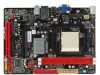
JUSB PWR2 JUSB2 JUSB3 JCMOS1 Super I/O SATA2 SATA1 JSFAN JPANEL1 4 Motherboard Manual 1.5 MOTHERBOARD LAYOUT JKB MS JKB_PWR JATXP WR4 J ATXPW R1 So ck et A M 3 JVGA DDR3_A1 DDR3_B1 IDE J USB1 JCFAN JUSBLA N1 JUSBPWR1 JA UDIO1 BAT1 GeForce 7025/ nForce 630a LAN JAU DIOF Codec JPRNT PEX16_1 BIOS PCI1 Note: ■ represents the 1st pin.
JUSB PWR2 JUSB2 JUSB3 JCMOS1 Super I/O SATA2 SATA1 JSFAN JPANEL1 4 Motherboard Manual 1.5 MOTHERBOARD LAYOUT JKB MS JKB_PWR JATXP WR4 J ATXPW R1 So ck et A M 3 JVGA DDR3_A1 DDR3_B1 IDE J USB1 JCFAN JUSBLA N1 JUSBPWR1 JA UDIO1 BAT1 GeForce 7025/ nForce 630a LAN JAU DIOF Codec JPRNT PEX16_1 BIOS PCI1 Note: ■ represents the 1st pin.

Setup Manual
Page 8
Connect the CPU FAN power cable to complete the installation. This completes the installation. 6 Step 4: Put the CPU Fan on the CPU and buckle it. Motherboard Manual Step 3: Hold the CPU down firmly, and then close the lever toward direct B to the JCFAN.
Connect the CPU FAN power cable to complete the installation. This completes the installation. 6 Step 4: Put the CPU Fan on the CPU and buckle it. Motherboard Manual Step 3: Hold the CPU down firmly, and then close the lever toward direct B to the JCFAN.

Setup Manual
Page 10
Align a DIMM on the slot so that the notch on the DIMM matches the break on the Slot. 2. DDR3 _A1 DDR3 _B1 Motherboard Manual 2.3 INSTALLING SYSTEM MEMORY A. Insert the DIMM vertically and firmly into the slot until the retaining chip snap back in place and the DIMM is properly seated. 8 Memory Modules 1. Unlock a DIMM slot by pressing the retaining clips outward.
Align a DIMM on the slot so that the notch on the DIMM matches the break on the Slot. 2. DDR3 _A1 DDR3 _B1 Motherboard Manual 2.3 INSTALLING SYSTEM MEMORY A. Insert the DIMM vertically and firmly into the slot until the retaining chip snap back in place and the DIMM is properly seated. 8 Memory Modules 1. Unlock a DIMM slot by pressing the retaining clips outward.

Setup Manual
Page 12
Motherboard Manual 2.4 CONNECTORS AND SLOTS IDE: IDE/ATAPI Connector The motherboard has a 32-bit Enhanced PCI IDE Controller that provides PIO Mode 0~4, Bus Master, and Ultra DMA 33/66/100/133 functionality. The IDE connector can connect a master and a slave drive, so you can connect up to two drives. 40 39 21 JATXPWR4: ATX Power Source Connector This connect provides +12V to CPU power circuit. 4 3 1 2 Pin Assignment 1 +12V 2 +12V 3 Ground 4 Ground 10
Motherboard Manual 2.4 CONNECTORS AND SLOTS IDE: IDE/ATAPI Connector The motherboard has a 32-bit Enhanced PCI IDE Controller that provides PIO Mode 0~4, Bus Master, and Ultra DMA 33/66/100/133 functionality. The IDE connector can connect a master and a slave drive, so you can connect up to two drives. 40 39 21 JATXPWR4: ATX Power Source Connector This connect provides +12V to CPU power circuit. 4 3 1 2 Pin Assignment 1 +12V 2 +12V 3 Ground 4 Ground 10
Setup Manual
Page 14
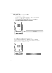
PEX16_1 PCI1: Peripheral Component Interconnect Slot This motherboard is designated as 32 bits. This PCI slot is equipped with 1 standard PCI slot. PCI1 12 Maximum theoretical realized bandwidth of 4GB/s simultaneously per direction, for expansion cards. Motherboard Manual PEX16_1: PCI-Express Gen2 x16 Slot - PCI-Express supports a raw bit-rate of 8GB/s totally. - PCI stands for Peripheral Component Interconnect, and it is a bus standard for an aggregate of 2.5Gb/s on the data pins. - 2X bandwidth over the traditional PCI architecture. PCI-Express 1.0a compliant. -
PEX16_1 PCI1: Peripheral Component Interconnect Slot This motherboard is designated as 32 bits. This PCI slot is equipped with 1 standard PCI slot. PCI1 12 Maximum theoretical realized bandwidth of 4GB/s simultaneously per direction, for expansion cards. Motherboard Manual PEX16_1: PCI-Express Gen2 x16 Slot - PCI-Express supports a raw bit-rate of 8GB/s totally. - PCI stands for Peripheral Component Interconnect, and it is a bus standard for an aggregate of 2.5Gb/s on the data pins. - 2X bandwidth over the traditional PCI architecture. PCI-Express 1.0a compliant. -

Setup Manual
Page 16
... a PCI to connect additional USB cable on the PC front panel, and also can be connected with transfer rate of 3.0Gb/s. Motherboard Manual JUSB2/JUSB3: Headers for USB 2.0 Ports at Front Panel These headers allow user to SATA Controller with 2 channels SATA interface, it satisfies the SATA 2.0 spec ...
... a PCI to connect additional USB cable on the PC front panel, and also can be connected with transfer rate of 3.0Gb/s. Motherboard Manual JUSB2/JUSB3: Headers for USB 2.0 Ports at Front Panel These headers allow user to SATA Controller with 2 channels SATA interface, it satisfies the SATA 2.0 spec ...

Setup Manual
Page 18
Motherboard Manual JPRNT: Printer Port Connector This header allows you to connect printer port on the PC. 2 26 1 25 Pin Assignment 1 -Strobe 2 -ALF 3 Data 0 4 -Error 5 Data 1 6 -Init 7 Data 2 8 -Scltin 9 Data 3 10 Ground 11 Data 4 12 Ground 13 Data 5 Pin Assignment 14 Ground 15 Data 6 16 Ground 17 Data 7 18 Ground 19 -ACK 20 Ground 21 Busy 22 Ground 23 PE 24 Ground 25 SCLT 26 Key JKB_PWR: Power Source Header for PS/2 Keyboard and Mouse 1 3 1 3 Pin 1-2 close +5V for PS/2 keyboard and mouse. 1 3 Pin 2-3 close +5V STB for PS/2 keyboard and mouse. 16
Motherboard Manual JPRNT: Printer Port Connector This header allows you to connect printer port on the PC. 2 26 1 25 Pin Assignment 1 -Strobe 2 -ALF 3 Data 0 4 -Error 5 Data 1 6 -Init 7 Data 2 8 -Scltin 9 Data 3 10 Ground 11 Data 4 12 Ground 13 Data 5 Pin Assignment 14 Ground 15 Data 6 16 Ground 17 Data 7 18 Ground 19 -ACK 20 Ground 21 Busy 22 Ground 23 PE 24 Ground 25 SCLT 26 Key JKB_PWR: Power Source Header for PS/2 Keyboard and Mouse 1 3 1 3 Pin 1-2 close +5V for PS/2 keyboard and mouse. 1 3 Pin 2-3 close +5V STB for PS/2 keyboard and mouse. 16

Setup Manual
Page 20
Depending on the system environment. If any fault tolerance. Motherboard Manual CHAPTER 4: RAID FUNCTIONS 4.1 OPERATING SYSTEM Supports Windows XP, Windows Vista, and Windows 7. 4.2 RAID ARRAYS RAID supports the following types of RAID arrays: RAID 0: RAID 0 defines a ...
Depending on the system environment. If any fault tolerance. Motherboard Manual CHAPTER 4: RAID FUNCTIONS 4.1 OPERATING SYSTEM Supports Windows XP, Windows Vista, and Windows 7. 4.2 RAID ARRAYS RAID supports the following types of RAID arrays: RAID 0: RAID 0 defines a ...

Setup Manual
Page 22
...after you insert the Driver CD, please use file browser to locate and execute the file SETUP.EXE under your motherboard and operating system. Motherboard Manual CHAPTER 5: USEFUL HELP 5.1 DRIVER INSTALLATION NOTE After you installed your operating system, please insert the Fully Setup Driver... CD into your optical drive and install the driver for available manual. Note: If this window didn't show up after you ...
...after you insert the Driver CD, please use file browser to locate and execute the file SETUP.EXE under your motherboard and operating system. Motherboard Manual CHAPTER 5: USEFUL HELP 5.1 DRIVER INSTALLATION NOTE After you installed your operating system, please insert the Fully Setup Driver... CD into your optical drive and install the driver for available manual. Note: If this window didn't show up after you ...
Setup Manual
Page 24
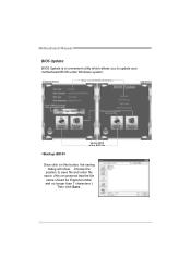
AWARD BIOS Show current BIOS information AMI BIOS Clear CMOS function (Only for AWARD BIOS) Save current BIOS to save file and enter file name. (We recommend that the file name should be English/number and no longer than 7 characters.) Then click Save. 22 Choose the position to a .bin file Update BIOS with a BIOS file Once click on this button, the saving dialog will show. Motherboard Manual BIOS Update BIOS Update is a convenient utility which allows you to update your motherboard BIOS under Windows system.
AWARD BIOS Show current BIOS information AMI BIOS Clear CMOS function (Only for AWARD BIOS) Save current BIOS to save file and enter file name. (We recommend that the file name should be English/number and no longer than 7 characters.) Then click Save. 22 Choose the position to a .bin file Update BIOS with a BIOS file Once click on this button, the saving dialog will show. Motherboard Manual BIOS Update BIOS Update is a convenient utility which allows you to update your motherboard BIOS under Windows system.

Setup Manual
Page 26
... is fulfilling with the CPU surface. 2. Clear the CMOS data. (See "Close CMOS Header: JCMOS1" section) 2. Wait for seconds. 2. Motherboard Manual 5.3 EXTRA INFORMATION CPU Overheated If the system shutdown automatically after power on system for seconds. 3. CPU fan speed is rotated normally. 3. When ...the CPU is placed evenly with the CPU speed. The CPU cooler surface is over heated, the motherboard will shutdown automatically to relief the CPU protection function. 1. Power on the system again. 24 In this case, please double check:...
... is fulfilling with the CPU surface. 2. Clear the CMOS data. (See "Close CMOS Header: JCMOS1" section) 2. Wait for seconds. 2. Motherboard Manual 5.3 EXTRA INFORMATION CPU Overheated If the system shutdown automatically after power on system for seconds. 3. CPU fan speed is rotated normally. 3. When ...the CPU is placed evenly with the CPU speed. The CPU cooler surface is over heated, the motherboard will shutdown automatically to relief the CPU protection function. 1. Power on the system again. 24 In this case, please double check:...

Setup Manual
Page 28
... correct information is no power in . work 3. Run SETUP program and select correct drive types. Call the drive manufacturers for compatibility with other drives. 26 Motherboard Manual 5.5 TROUBLESHOOTING Probable Solution 1. Replace cable. Make sure both ends of are on, power indicator lights are lit, the DIMM, press down at any time. Review...
... correct information is no power in . work 3. Run SETUP program and select correct drive types. Call the drive manufacturers for compatibility with other drives. 26 Motherboard Manual 5.5 TROUBLESHOOTING Probable Solution 1. Replace cable. Make sure both ends of are on, power indicator lights are lit, the DIMM, press down at any time. Review...
Bios Setup
Page 2
... support Version 1.0/2.0 of the EPA Green PC specification. The rest of this motherboard. Power management features are supported. N68S3B BIOS Manual BIOS Setup Introduction The purpose of this manual is to describe the settings in the AMI BIOS Setup program on this manual will to guide you through the options and settings in BIOS Setup...
... support Version 1.0/2.0 of the EPA Green PC specification. The rest of this motherboard. Power management features are supported. N68S3B BIOS Manual BIOS Setup Introduction The purpose of this manual is to describe the settings in the AMI BIOS Setup program on this manual will to guide you through the options and settings in BIOS Setup...

Bios Setup
Page 3
... the BIOS firmware is providing a brief description of the motherboard. The BIOS information described in this manual is for any settings, please load the default settings to ensure optimum performance of the selected item. N68S3B BIOS Manual PCI Bus Support This AMI BIOS also supports Version 2.3 ...of this is being continuously updated. If the system becomes unstable after changing any mistakes found in this manual. We will see General Help description ...
... the BIOS firmware is providing a brief description of the motherboard. The BIOS information described in this manual is for any settings, please load the default settings to ensure optimum performance of the selected item. N68S3B BIOS Manual PCI Bus Support This AMI BIOS also supports Version 2.3 ...of this is being continuously updated. If the system becomes unstable after changing any mistakes found in this manual. We will see General Help description ...
Bios Setup
Page 15
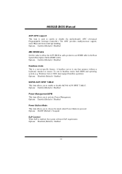
... operation. Options: On/Off (Default) / Suspend EuP Control When EuP is used to enable or disable the motherboard's APIC (Advanced Programmable Interrupt Controller). To run in the Root System Description Table (RSDT) table. N68S3B BIOS Manual ACPI APIC support This item is enabled, the system will meet EuP requirement. The APIC provides multiprocessor...
... operation. Options: On/Off (Default) / Suspend EuP Control When EuP is used to enable or disable the motherboard's APIC (Advanced Programmable Interrupt Controller). To run in the Root System Description Table (RSDT) table. N68S3B BIOS Manual ACPI APIC support This item is enabled, the system will meet EuP requirement. The APIC provides multiprocessor...
Bios Setup
Page 16
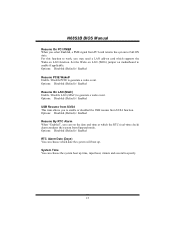
... Time You can choose the system boot up . For this function to work, you may need a LAN add-on card which supports the Wake on motherboard to specify. 15 Options: Disabled (Default) / Enabled Resume By RT C Alarm When "Enabled", you can choose which the RTC (real-time clock) alarm ...minute and second to enable if applicable. Options: Disabled (Default) / Enabled USB Resume from S3/S4 This item allows you to Full ON state. N68S3B BIOS Manual Resume On PCI PME# When you select Enabled, a PME signal from PCI card returns the system to enable or disabled the USB resume from Suspend...
... Time You can choose the system boot up . For this function to work, you may need a LAN add-on card which supports the Wake on motherboard to specify. 15 Options: Disabled (Default) / Enabled Resume By RT C Alarm When "Enabled", you can choose which the RTC (real-time clock) alarm ...minute and second to enable if applicable. Options: Disabled (Default) / Enabled USB Resume from S3/S4 This item allows you to Full ON state. N68S3B BIOS Manual Resume On PCI PME# When you select Enabled, a PME signal from PCI card returns the system to enable or disabled the USB resume from Suspend...


