Bios Setup
Page 2
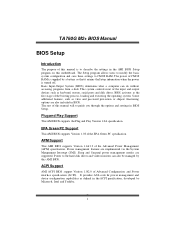
... Int errupt (SMI). It provides ASL code for pow er manag ement and device con figuration capabilities as keyboard, mouse, serial ports and disk drives. TA760G M2+ BIOS Manual BIOS Setup Introduction T he purpose of this manual is turned off. T he power of CMOS RAM is supplied by a battery so that it... and Pla y Support T his AMI BIOS supports Version 1.1&1.2 of the input and output devices such as defined in the AMI BIOS Setup program on this motherboard.
... Int errupt (SMI). It provides ASL code for pow er manag ement and device con figuration capabilities as keyboard, mouse, serial ports and disk drives. TA760G M2+ BIOS Manual BIOS Setup Introduction T he purpose of this manual is turned off. T he power of CMOS RAM is supplied by a battery so that it... and Pla y Support T his AMI BIOS supports Version 1.1&1.2 of the input and output devices such as defined in the AMI BIOS Setup program on this motherboard.
Bios Setup
Page 3
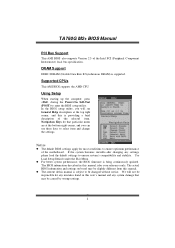
.... The actual BIOS information and settings on board may be chang ed without notice. Supported CP Us T his AMI BIOS also supports Version 2.3 of the motherboard. TA760G M2+ BIOS Manual PCI Bus Support T his AMI BIOS supports the AMD CPU. Using Setup When starting up the computer, press during the Power-On Self...
.... The actual BIOS information and settings on board may be chang ed without notice. Supported CP Us T his AMI BIOS also supports Version 2.3 of the motherboard. TA760G M2+ BIOS Manual PCI Bus Support T his AMI BIOS supports the AMD CPU. Using Setup When starting up the computer, press during the Power-On Self...
Bios Setup
Page 13
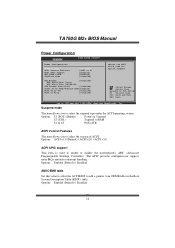
... disable the motherboard's APIC (Advan ced Programmable Interrupt Controller). Options: Enabled (Default) / Disabled AMI OEMB table Set this value to allow the ACPIBIOS to add a pointer to Sub Scr een F1 G eneral Help F1 0 S ave and Exit ES C E xit vxx.xx (C)C opyright 198 5-200x, Amer ican Megatre nds, Inc. TA760G M2+ BIOS Manual...
... disable the motherboard's APIC (Advan ced Programmable Interrupt Controller). Options: Enabled (Default) / Disabled AMI OEMB table Set this value to allow the ACPIBIOS to add a pointer to Sub Scr een F1 G eneral Help F1 0 S ave and Exit ES C E xit vxx.xx (C)C opyright 198 5-200x, Amer ican Megatre nds, Inc. TA760G M2+ BIOS Manual...
Setup Manual
Page 2
Table of Contents Chapter 1: Introduction 1 1.1 Before You Start 1 1.2 Package Checklist 1 1.3 Motherboard Features 2 1.4 Rear Panel Connectors 3 1.5 Motherboard Layout 4 Chapter 2: Hardware Installation 5 2.1 Installing Central Processing Unit (CPU 5 2.2 FAN Headers 7 2.3 Installing System Memory 8 2.4 Connectors and Slots 10 Chapter 3: Headers & Jumpers Setup 12 3.1 How to ...
Table of Contents Chapter 1: Introduction 1 1.1 Before You Start 1 1.2 Package Checklist 1 1.3 Motherboard Features 2 1.4 Rear Panel Connectors 3 1.5 Motherboard Layout 4 Chapter 2: Hardware Installation 5 2.1 Installing Central Processing Unit (CPU 5 2.2 FAN Headers 7 2.3 Installing System Memory 8 2.4 Connectors and Slots 10 Chapter 3: Headers & Jumpers Setup 12 3.1 How to ...
Setup Manual
Page 3
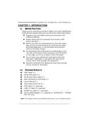
... the case after installation. Loose parts will cause short circuits which may be different due to area or your motherboard version. 1 TA780G M2+/TA780G M2+ HP/TA760G M2+ CHAPTER 1: INTRODUCTION 1.1 BEFORE YOU START Thank you take the motherboard out from dangerous area, such as heat source, humid air and water. 1.2 PACKAGE CHECKLIST HDD Cable X 1 Serial ATA...
... the case after installation. Loose parts will cause short circuits which may be different due to area or your motherboard version. 1 TA780G M2+/TA780G M2+ HP/TA760G M2+ CHAPTER 1: INTRODUCTION 1.1 BEFORE YOU START Thank you take the motherboard out from dangerous area, such as heat source, humid air and water. 1.2 PACKAGE CHECKLIST HDD Cable X 1 Serial ATA...
Setup Manual
Page 4
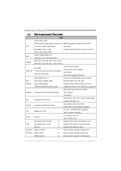
... and Cool=n=Quiet Phenom Max. Power: 95W Support HyperTransport 3.0 FSB Supports up to 5.2 GT/s Bandwidth Chipset AMD 780G (TA760G M2+: AMD 760G) AMD SB700 (TA760G M2+: AMD SB710) ITE 8718F Super I/O Provides the most commonly used legacy Super I/O functionality Low Pin Count Interface Environment Control ... connector supports 2 Floppy drives x1 Each connector supports 2 IDE device SATA Connector x6 Each connector supports 1 SATA devices 2 Motherboard Manual 1.3 MOTHERBOARD FEATURES SPEC Socket AM2+ / AM2 AMD Athlon 64 / Athlon 64 FX / Athlon 64 x2 AMD 64 Architecture enables 32...
... and Cool=n=Quiet Phenom Max. Power: 95W Support HyperTransport 3.0 FSB Supports up to 5.2 GT/s Bandwidth Chipset AMD 780G (TA760G M2+: AMD 760G) AMD SB700 (TA760G M2+: AMD SB710) ITE 8718F Super I/O Provides the most commonly used legacy Super I/O functionality Low Pin Count Interface Environment Control ... connector supports 2 Floppy drives x1 Each connector supports 2 IDE device SATA Connector x6 Each connector supports 1 SATA devices 2 Motherboard Manual 1.3 MOTHERBOARD FEATURES SPEC Socket AM2+ / AM2 AMD Athlon 64 / Athlon 64 FX / Athlon 64 x2 AMD 64 Architecture enables 32...
Setup Manual
Page 6
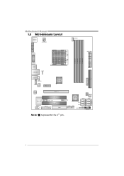
Motherboard Manual 1.5 MOTHERBOARD LAYOUT JKBM S1 JATXPWR2 JCFAN1 JATXPWR1 S ocket A M2+ DVI VG A D IMMA1 D IMMB1 D IMMA2 D IMMB2 JUSB1 JUSBL AN1 JUSBV1 BATTERY IDE1 JAUDIO1 JAUDIOF 1 JCDIN1 LAN PEX1 _1 AMD 780G/ 760 G Cod ec P EX16 _1 Super I/O JCOM1 PCI1 JS PDI F_ O UT1 PCI2 JPRNT1 FDD1 JUSB4 AMD SB 7 00/ SB710 JSFAN1 SATA5 SATA6 SATA3 JUSB3 JUSB2 SATA1 JUSBV2 JCMOS1 SATA2 JPANEL1 BIOS Note: ■ represents the 1st pin. SATA4 4
Motherboard Manual 1.5 MOTHERBOARD LAYOUT JKBM S1 JATXPWR2 JCFAN1 JATXPWR1 S ocket A M2+ DVI VG A D IMMA1 D IMMB1 D IMMA2 D IMMB2 JUSB1 JUSBL AN1 JUSBV1 BATTERY IDE1 JAUDIO1 JAUDIOF 1 JCDIN1 LAN PEX1 _1 AMD 780G/ 760 G Cod ec P EX16 _1 Super I/O JCOM1 PCI1 JS PDI F_ O UT1 PCI2 JPRNT1 FDD1 JUSB4 AMD SB 7 00/ SB710 JSFAN1 SATA5 SATA6 SATA3 JUSB3 JUSB2 SATA1 JUSBV2 JCMOS1 SATA2 JPANEL1 BIOS Note: ■ represents the 1st pin. SATA4 4
Setup Manual
Page 8
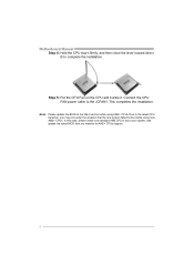
Note: Please update the BIOS to the latest version while using new AM2+ CPUs. Motherboard Manual Step 4: Hold the CPU down firmly, and then close the lever toward direct B to the JCFAN1. Connect the CPU FAN power cable to complete ...
Note: Please update the BIOS to the latest version while using new AM2+ CPUs. Motherboard Manual Step 4: Hold the CPU down firmly, and then close the lever toward direct B to the JCFAN1. Connect the CPU FAN power cable to complete ...
Setup Manual
Page 10
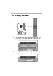
Memory Modules 1. Unlock a DIMM slot by pressing the retaining clips outward. Align a DIMM on the slot such that the notch on the DIMM matches the break on the Slot. 2. Insert the DIMM vertically and firmly into the slot until the retaining chip snap back in place and the DIMM is properly seated. 8 DIMMA1 DIMMB1 DIMMA2 DIMMB2 Motherboard Manual 2.3 INSTALLING SYSTEM MEMORY A.
Memory Modules 1. Unlock a DIMM slot by pressing the retaining clips outward. Align a DIMM on the slot such that the notch on the DIMM matches the break on the Slot. 2. Insert the DIMM vertically and firmly into the slot until the retaining chip snap back in place and the DIMM is properly seated. 8 DIMMA1 DIMMB1 DIMMA2 DIMMB2 Motherboard Manual 2.3 INSTALLING SYSTEM MEMORY A.
Setup Manual
Page 11
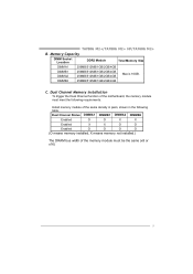
.../4GB C. Dual Channel Memory installation To trigger the Dual Channel function of the motherboard, the memory module must meet the following requirements: Install memory module of the memory module must be the same (x8 or x16) 9 TA780G M2+/TA780G M2+ HP/TA760G M2+ B. Dual Channel Status DIMMA1 DIMMB1 DIMMA2 DIMMB2 Enabled O O X X Enabled X X O O Enabled O O O O (O means memory...
.../4GB C. Dual Channel Memory installation To trigger the Dual Channel function of the motherboard, the memory module must meet the following requirements: Install memory module of the memory module must be the same (x8 or x16) 9 TA780G M2+/TA780G M2+ HP/TA760G M2+ B. Dual Channel Status DIMMA1 DIMMB1 DIMMA2 DIMMB2 Enabled O O X X Enabled X X O O Enabled O O O O (O means memory...

Setup Manual
Page 12
This connector supports the provided floppy drive ribbon cable. 2 34 1 33 IDE1: Hard Disk Connector The motherboard has a 32-bit Enhanced PCI IDE Controller that supports 360K, 720K, 1.2M, 1.44M and 2.88M floppy disk types. The IDE connectors can connect a master and a slave drive, so you can connect up to two hard disk drives. 40 39 21 10 Motherboard Manual 2.4 CONNECTORS AND SLOTS FDD1: Floppy Disk Connector The motherboard provides a standard floppy disk connector that provides PIO Mode 0~4, Bus Master, and Ultra DMA 33/66/100/133 functionality.
This connector supports the provided floppy drive ribbon cable. 2 34 1 33 IDE1: Hard Disk Connector The motherboard has a 32-bit Enhanced PCI IDE Controller that supports 360K, 720K, 1.2M, 1.44M and 2.88M floppy disk types. The IDE connectors can connect a master and a slave drive, so you can connect up to two hard disk drives. 40 39 21 10 Motherboard Manual 2.4 CONNECTORS AND SLOTS FDD1: Floppy Disk Connector The motherboard provides a standard floppy disk connector that provides PIO Mode 0~4, Bus Master, and Ultra DMA 33/66/100/133 functionality.

Setup Manual
Page 13
... 2 standard PCI slots. PCI-Express Gen2 supports a raw bit-rate of 16GB/s totally. PCI1 PCI2 11 PEX1_1 PEX16_1 PCI1~PCI2: Peripheral Component Interconnect Slots This motherboard is designated as 32 bits. PEX1_1: PCI-Express Gen2 x1 Slot - Maximum theoretical realized bandwidth of 8GB/s simultaneously per direction; 1GB/s in total. - PCI stands... of 5.0Gb/s on the data pins. - 2X bandwidth over the PCI-Express 1.0 architecture. Data transfer bandwidth up to 500MB/s per direction, for expansion cards. TA780G M2+/TA780G M2+ HP/TA760G M2+ PEX16_1: PCI-Express Gen2 x16 Slot -
... 2 standard PCI slots. PCI-Express Gen2 supports a raw bit-rate of 16GB/s totally. PCI1 PCI2 11 PEX1_1 PEX16_1 PCI1~PCI2: Peripheral Component Interconnect Slots This motherboard is designated as 32 bits. PEX1_1: PCI-Express Gen2 x1 Slot - Maximum theoretical realized bandwidth of 8GB/s simultaneously per direction; 1GB/s in total. - PCI stands... of 5.0Gb/s on the data pins. - 2X bandwidth over the PCI-Express 1.0 architecture. Data transfer bandwidth up to 500MB/s per direction, for expansion cards. TA780G M2+/TA780G M2+ HP/TA760G M2+ PEX16_1: PCI-Express Gen2 x16 Slot -
Setup Manual
Page 14
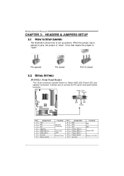
... (+) Power LED (+) Power LED (-) Power button Ground Function N/A N/A Power LED Power-on pins, the jumper is "close", if not, that means the jumper is "open". Motherboard Manual CHAPTER 3: HEADERS & JUMPERS SETUP 3.1 HOW TO SETUP JUMPERS The illustration shows how to connect the PC case's front panel switch functions. Pin opened Pin...
... (+) Power LED (+) Power LED (-) Power button Ground Function N/A N/A Power LED Power-on pins, the jumper is "close", if not, that means the jumper is "open". Motherboard Manual CHAPTER 3: HEADERS & JUMPERS SETUP 3.1 HOW TO SETUP JUMPERS The illustration shows how to connect the PC case's front panel switch functions. Pin opened Pin...
Setup Manual
Page 16
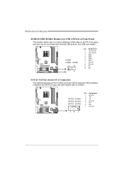
Motherboard Manual JUSB2/JUSB3/JUSB4: Headers for USB 2.0 Ports at Front Panel This header allows user to SATA Controller with 6 channels SATA interface, it satisfies the ... JUSB3 JUSB2 2 10 19 Pin Assignment 1 +5V (fused) 2 +5V (fused) 3 USB4 USB5 USB+ 6 USB+ 7 Ground 8 Ground 9 NC 10 Key SATA1~SATA6: Serial ATA Connectors The motherboard has a PCI to connect additional USB cable on the PC front panel, and also can be connected with transfer rate of 3.0Gb/s. SATA5 SATA6 SATA3...
Motherboard Manual JUSB2/JUSB3/JUSB4: Headers for USB 2.0 Ports at Front Panel This header allows user to SATA Controller with 6 channels SATA interface, it satisfies the ... JUSB3 JUSB2 2 10 19 Pin Assignment 1 +5V (fused) 2 +5V (fused) 3 USB4 USB5 USB+ 6 USB+ 7 Ground 8 Ground 9 NC 10 Key SATA1~SATA6: Serial ATA Connectors The motherboard has a PCI to connect additional USB cable on the PC front panel, and also can be connected with transfer rate of 3.0Gb/s. SATA5 SATA6 SATA3...

Setup Manual
Page 18
... desired password or clear the CMOS data. 16 Set the jumper to "Pin 2-3 close ". 5. Wait for five seconds. 4. Motherboard Manual JCDIN1: CD-ROM Audio-in Connector This connector allows user to avoid damaging the motherboard. 13 Pin 1-2 Close: Normal Operation (default). 13 13 Pin 2-3 Close: Clear CMOS data. ※ Clear CMOS Procedures...
... desired password or clear the CMOS data. 16 Set the jumper to "Pin 2-3 close ". 5. Wait for five seconds. 4. Motherboard Manual JCDIN1: CD-ROM Audio-in Connector This connector allows user to avoid damaging the motherboard. 13 Pin 1-2 Close: Normal Operation (default). 13 13 Pin 2-3 Close: Clear CMOS data. ※ Clear CMOS Procedures...
Setup Manual
Page 19
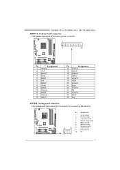
TA780G M2+/TA780G M2+ HP/TA760G M2+ JPRNT1: Printer Port Connector This header allows you to send 9 Ring indicator 10 NC 1 9 17 Pin Assignment 1 Carrier detect 2 Received data 3 Transmitted data 4 Data terminal ... 17 Data 7 18 Ground 19 -ACK 20 Ground 21 Busy 22 Ground 23 PE 24 Ground 25 SCLT 26 Key JCOM1: Serial port Connector The motherboard has a Serial Port Connector for connecting RS-232 Port.
TA780G M2+/TA780G M2+ HP/TA760G M2+ JPRNT1: Printer Port Connector This header allows you to send 9 Ring indicator 10 NC 1 9 17 Pin Assignment 1 Carrier detect 2 Received data 3 Transmitted data 4 Data terminal ... 17 Data 7 18 Ground 19 -ACK 20 Ground 21 Busy 22 Ground 23 PE 24 Ground 25 SCLT 26 Key JCOM1: Serial port Connector The motherboard has a Serial Port Connector for connecting RS-232 Port.
Setup Manual
Page 20
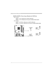
Motherboard Manual JUSBV1/JUSBV2: Power Source Headers for USB Ports Pin 1-2 Close: JUSBV1: +5V for USB ports at front panel (JUSB2/JUSB3/JUSB4). JUSBV2: +5V STB for USB ports at JUSB1/JUSBLAN1. Pin 2-3 Close: JUSBV1: +5V STB for USB ports at JUSB1/JUSBLAN1. JUSBV2: +5V for USB ports at front panel (JUSB2/JUSB3/JUSB4). JUSBV1 1 3 13 JUSBV2 13 1 3 Pin 1-2 close 13 1 3 Pin 2-3 close 18
Motherboard Manual JUSBV1/JUSBV2: Power Source Headers for USB Ports Pin 1-2 Close: JUSBV1: +5V for USB ports at front panel (JUSB2/JUSB3/JUSB4). JUSBV2: +5V STB for USB ports at JUSB1/JUSBLAN1. Pin 2-3 Close: JUSBV1: +5V STB for USB ports at JUSB1/JUSBLAN1. JUSBV2: +5V for USB ports at front panel (JUSB2/JUSB3/JUSB4). JUSBV1 1 3 13 JUSBV2 13 1 3 Pin 1-2 close 13 1 3 Pin 2-3 close 18
Setup Manual
Page 22
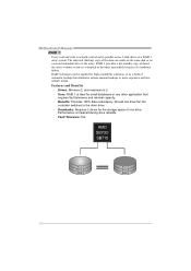
... is actually carried out in parallel across 2 disk drives in the array. Should one drive. Block 1 Block 2 Block 3 Block 1 Block 2 Block 3 20 Fault Tolerance: Yes. Motherboard Manual RAID 1: Every read and write is 2. - Features and Benefits - Uses: RAID 1 is impaired during drive rebuilds. - Benefits: Provides 100% data redundancy. Performance is ideal...
... is actually carried out in parallel across 2 disk drives in the array. Should one drive. Block 1 Block 2 Block 3 Block 1 Block 2 Block 3 20 Fault Tolerance: Yes. Motherboard Manual RAID 1: Every read and write is 2. - Features and Benefits - Uses: RAID 1 is impaired during drive rebuilds. - Benefits: Provides 100% data redundancy. Performance is ideal...
Setup Manual
Page 24
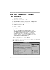
... cause system to the BIOS Manual in below in this manual. For better system performance, the BIOS firmware is for both Elite and Casual overclockers. Motherboard Manual CHAPTER 5: T-SERIES BIOS & SOFTWARE 5.1 T-SERIES BIOS T-Series BIOS Features Overclocking Navigator Engine (O.N.E.) Memory Integration Test (M.I.T., under Overclock Navigator Engine) BIO-Flasher: Update BIOS file...
... cause system to the BIOS Manual in below in this manual. For better system performance, the BIOS firmware is for both Elite and Casual overclockers. Motherboard Manual CHAPTER 5: T-SERIES BIOS & SOFTWARE 5.1 T-SERIES BIOS T-Series BIOS Features Overclocking Navigator Engine (O.N.E.) Memory Integration Test (M.I.T., under Overclock Navigator Engine) BIO-Flasher: Update BIOS file...
Setup Manual
Page 26
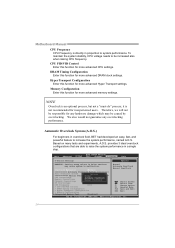
Therefore, we will not be responsible for more advanced Hyper Transport settings. Motherboard Manual CPU Frequency CPU Frequency is an optional process, but not a "must-do" process; Hyper Transport Configuration Enter this function for any overclocking performance. provides 3 ...
Therefore, we will not be responsible for more advanced Hyper Transport settings. Motherboard Manual CPU Frequency CPU Frequency is an optional process, but not a "must-do" process; Hyper Transport Configuration Enter this function for any overclocking performance. provides 3 ...

