Setup Manual
Page 1
... no representations or warranties with respect to the contents here and specially disclaims any implied warranties of this user's manual is subject to notify any purpose. TA770 A2+ Setup Manual FCC Information and Copyright This equipment has been tested and found in a particular installation. There is not allowed without...be changed without notice and we will not occur in this publication and to make changes to revise this user's manual. Further the vendor reserves the right to the contents here without first obtaining the vendor's approval in a residential installation.
... no representations or warranties with respect to the contents here and specially disclaims any implied warranties of this user's manual is subject to notify any purpose. TA770 A2+ Setup Manual FCC Information and Copyright This equipment has been tested and found in a particular installation. There is not allowed without...be changed without notice and we will not occur in this publication and to make changes to revise this user's manual. Further the vendor reserves the right to the contents here without first obtaining the vendor's approval in a residential installation.
Setup Manual
Page 3
... for ATX Case X 1 User's Manual X 1 Fully Setup Driver CD X 1 FDD Cable X 1 (optional) USB 2.0 Cable X1 (optional) S/PDIF out Cable X 1 (optional) Note: The package contents may damage the equipment. „ Keep the computer from anti-static bag, ground yourself properly by area or your motherboard version. 1 CHAPTER 1: INTRODUCTION TA770 A2+ 1.1 BEFORE YOU START Thank...
... for ATX Case X 1 User's Manual X 1 Fully Setup Driver CD X 1 FDD Cable X 1 (optional) USB 2.0 Cable X1 (optional) S/PDIF out Cable X 1 (optional) Note: The package contents may damage the equipment. „ Keep the computer from anti-static bag, ground yourself properly by area or your motherboard version. 1 CHAPTER 1: INTRODUCTION TA770 A2+ 1.1 BEFORE YOU START Thank...

Setup Manual
Page 4
... (Onboard) AMD SB600 (Onboard) Jmicro JMB362 (eSATA) (optional) Jmicro JMB362 (eSATA) (optional) Data transfer rates up to 3 Gb/s. Data transfer rates up to 3 Gb/s. Motherboard Manual 1.3 MOTHERBOARD FEATURES Ver 5.x Ver 6.x Socket AM2 / AM2+ Socket AM2 / AM2+ AMD Athlon 64 / Athlon 64 FX / Athlon 64 X2 / AMD Athlon 64 / Athlon 64 FX...
... (Onboard) AMD SB600 (Onboard) Jmicro JMB362 (eSATA) (optional) Jmicro JMB362 (eSATA) (optional) Data transfer rates up to 3 Gb/s. Data transfer rates up to 3 Gb/s. Motherboard Manual 1.3 MOTHERBOARD FEATURES Ver 5.x Ver 6.x Socket AM2 / AM2+ Socket AM2 / AM2+ AMD Athlon 64 / Athlon 64 FX / Athlon 64 X2 / AMD Athlon 64 / Athlon 64 FX...
Setup Manual
Page 6
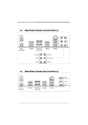
Motherboard Manual 1.4 REAR PANEL CONNECTORS (FOR VER 5.X) PS/2 Mouse LAN PS/2 Keyboard USBX2 eSATAX2 (Optional) USBX2 USBX2 Center Rear Side Line In Line Out Mic In 1.5 REAR PANEL CONNECTORS (FOR VER 6.X) PS/2 Mouse LA N PS/ 2 Ke ybo ar d USB X2 eSATAX2 (Op ti on al) USBX2 USBX2 Line In/ Surround Line Out Mic I n 1/ Bass/ Center 4
Motherboard Manual 1.4 REAR PANEL CONNECTORS (FOR VER 5.X) PS/2 Mouse LAN PS/2 Keyboard USBX2 eSATAX2 (Optional) USBX2 USBX2 Center Rear Side Line In Line Out Mic In 1.5 REAR PANEL CONNECTORS (FOR VER 6.X) PS/2 Mouse LA N PS/ 2 Ke ybo ar d USB X2 eSATAX2 (Op ti on al) USBX2 USBX2 Line In/ Surround Line Out Mic I n 1/ Bass/ Center 4
Setup Manual
Page 8
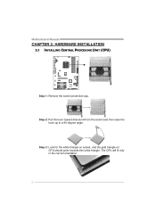
The CPU will fit only in the correct orientation. 6 Motherboard Manual CHAPTER 2: HARDWARE INSTALLATION 2.1 INSTALLING CENTRAL PROCESSING UNIT (CPU) Step 1: Remove the socket protection cap. Step 2: Pull the lever toward direction A from the socket and then raise the lever up to a 90-degree angle. Step 3: Look for the white triangle on socket, and the gold triangle on CPU should point towards this white triangle.
The CPU will fit only in the correct orientation. 6 Motherboard Manual CHAPTER 2: HARDWARE INSTALLATION 2.1 INSTALLING CENTRAL PROCESSING UNIT (CPU) Step 1: Remove the socket protection cap. Step 2: Pull the lever toward direction A from the socket and then raise the lever up to a 90-degree angle. Step 3: Look for the white triangle on socket, and the gold triangle on CPU should point towards this white triangle.
Setup Manual
Page 10
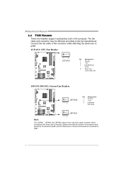
... 13 Pin Assignment 1 Ground 2 +12V 3 FAN RPM rate sense JSFAN1 13 Note: The JCFAN1、JSFAN1 and JSFAN2 support 4-pin and 3-pin head connector. Motherboard Manual 2.2 FAN HEADERS These fan headers support cooling-fans built in the computer. When connecting with wires onto connectors, please note that the red wire is...
... 13 Pin Assignment 1 Ground 2 +12V 3 FAN RPM rate sense JSFAN1 13 Note: The JCFAN1、JSFAN1 and JSFAN2 support 4-pin and 3-pin head connector. Motherboard Manual 2.2 FAN HEADERS These fan headers support cooling-fans built in the computer. When connecting with wires onto connectors, please note that the red wire is...
Setup Manual
Page 12
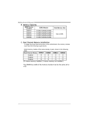
Motherboard Manual B. Memory Capacity DIMM Socket Location DDR2 Module DIMMA1 512MB/1024MB/2048MB DIMMB1 512MB/1024MB/2048MB DIMMA2 512MB/1024MB/2048MB DIMMB2 512MB/1024MB/2048MB Total Memory ...
Motherboard Manual B. Memory Capacity DIMM Socket Location DDR2 Module DIMMA1 512MB/1024MB/2048MB DIMMB1 512MB/1024MB/2048MB DIMMA2 512MB/1024MB/2048MB DIMMB2 512MB/1024MB/2048MB Total Memory ...
Setup Manual
Page 14
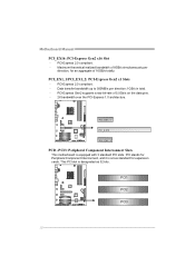
... bandwidth up to 500MB/s per direction, for expansion cards. PCI-Express 2.0 compliant. - Maximum theoretical realized bandwidth of 8GB/s simultaneously per direction; 1GB/s in total. - Motherboard Manual PCI_EX16: PCI-Express Gen2 x16 Slot - This PCI slot is equipped with 3 standard PCI slots.
... bandwidth up to 500MB/s per direction, for expansion cards. PCI-Express 2.0 compliant. - Maximum theoretical realized bandwidth of 8GB/s simultaneously per direction; 1GB/s in total. - Motherboard Manual PCI_EX16: PCI-Express Gen2 x16 Slot - This PCI slot is equipped with 3 standard PCI slots.
Setup Manual
Page 16
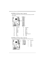
Motherboard Manual JATXPWR1: ATX Power Source Connector This connector allows user to connect 24-pin power connector on the ATX power supply. 12 24 1 13 Pin Assignment ...
Motherboard Manual JATXPWR1: ATX Power Source Connector This connector allows user to connect 24-pin power connector on the ATX power supply. 12 24 1 13 Pin Assignment ...
Setup Manual
Page 18
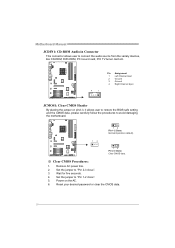
... five seconds. 4. Set the jumper to "Pin 1-2 close ". 3. Reset your desired password or clear the CMOS data. 16 Set the jumper to "Pin 2-3 close ". 5. Motherboard Manual JCDIN1: CD-ROM Audio-in Connector This connector allows user to connect the audio source from the variaty devices, like CD-ROM, DVD-ROM, PCI...
... five seconds. 4. Set the jumper to "Pin 1-2 close ". 3. Reset your desired password or clear the CMOS data. 16 Set the jumper to "Pin 2-3 close ". 5. Motherboard Manual JCDIN1: CD-ROM Audio-in Connector This connector allows user to connect the audio source from the variaty devices, like CD-ROM, DVD-ROM, PCI...
Setup Manual
Page 20
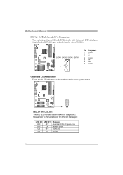
... for different messages: LED_D2 OFF OFF ON ON LED_D1 OFF ON OFF ON Message Abnormal: CPU / Chipset error. Please refer to show system status. Motherboard Manual SATA1~SATA4: Serial ATA Connectors The motherboard has a PCI to SATA Controller with 4 channels SATA interface, it satisfies the SATA 2.0 spec and with transfer rate...
... for different messages: LED_D2 OFF OFF ON ON LED_D1 OFF ON OFF ON Message Abnormal: CPU / Chipset error. Please refer to show system status. Motherboard Manual SATA1~SATA4: Serial ATA Connectors The motherboard has a PCI to SATA Controller with 4 channels SATA interface, it satisfies the SATA 2.0 spec and with transfer rate...
Setup Manual
Page 22
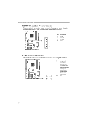
Motherboard Manual JATXPWR3: Auxiliary Power for Graphics This connector is an auxiliary power connection for connecting RS-232 Port. Pin Assignment 1 +12V 2 Ground 1 3 Ground 4 VCC 4 JCOM1: Serial port Connector The motherboard has a Serial Port Connector for graphics cards. Pin Assignment 1 Carrier detect 2 Received data 3 Transmitted data 4 Data terminal ready 5 Signal ground 6 Data set ready 7 Request to send 8 Clear to send 2 10 9 Ring indicator 10 Key 1 9 20 Exclusive power for the graphics card provides better graphics performance.
Motherboard Manual JATXPWR3: Auxiliary Power for Graphics This connector is an auxiliary power connection for connecting RS-232 Port. Pin Assignment 1 +12V 2 Ground 1 3 Ground 4 VCC 4 JCOM1: Serial port Connector The motherboard has a Serial Port Connector for graphics cards. Pin Assignment 1 Carrier detect 2 Received data 3 Transmitted data 4 Data terminal ready 5 Signal ground 6 Data set ready 7 Request to send 8 Clear to send 2 10 9 Ring indicator 10 Key 1 9 20 Exclusive power for the graphics card provides better graphics performance.

Setup Manual
Page 24
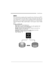
... that improves disk read and write times for parity. Drawbacks: Does not deliver any fault tolerance. If any drive in a RAID 0 array system. Motherboard Manual CHAPTER 4: RAID FUNCTIONS 4.1 OPERATION SYSTEM Supports Windows XP Home/Professional Edition and Windows VISTA. 4.2 RAID ARRAYS RAID supports the following types of RAID arrays: RAID...
... that improves disk read and write times for parity. Drawbacks: Does not deliver any fault tolerance. If any drive in a RAID 0 array system. Motherboard Manual CHAPTER 4: RAID FUNCTIONS 4.1 OPERATION SYSTEM Supports Windows XP Home/Professional Edition and Windows VISTA. 4.2 RAID ARRAYS RAID supports the following types of RAID arrays: RAID...
Setup Manual
Page 25
... requires fault tolerance and minimal capacity. Benefits: Provides 100% data redundancy. Block 1 Block 2 Block 3 Block 1 Block 2 Block 3 23 TA770 A2+ RAID 1: Every read and write is impaired during drive rebuilds. Fault Tolerance: Yes. The mirrored (backup) copy of the data can be ..., the controller switches to the other drive. Drawbacks: Requires 2 drives for small databases or any other application that eliminates tedious manual backups to more expensive and less reliable media. RAID techniques can reside on the same disk or on a second redundant drive in a...
... requires fault tolerance and minimal capacity. Benefits: Provides 100% data redundancy. Block 1 Block 2 Block 3 Block 1 Block 2 Block 3 23 TA770 A2+ RAID 1: Every read and write is impaired during drive rebuilds. Fault Tolerance: Yes. The mirrored (backup) copy of the data can be ..., the controller switches to the other drive. Drawbacks: Requires 2 drives for small databases or any other application that eliminates tedious manual backups to more expensive and less reliable media. RAID techniques can reside on the same disk or on a second redundant drive in a...
Setup Manual
Page 26
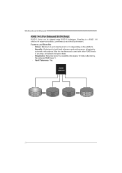
... Resulting in an array, and allows for spare disks. Drawbacks: Requires twice the available disk space for improved resiliency, performance and rebuild performance. Motherboard Manual RAID 1+0 (For Onboard SATA Only): RAID 1 drives can be simultaneously used with other RAID levels in a RAID 1+0 solution for data redundancy, the same as RAID...
... Resulting in an array, and allows for spare disks. Drawbacks: Requires twice the available disk space for improved resiliency, performance and rebuild performance. Motherboard Manual RAID 1+0 (For Onboard SATA Only): RAID 1 drives can be simultaneously used with other RAID levels in a RAID 1+0 solution for data redundancy, the same as RAID...
Setup Manual
Page 28
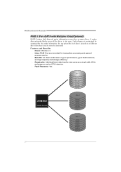
... 5 DATA 8 PARITY DATA 11 Disk 3 PARITY DATA 4 DATA 6 PARITY DATA 10 DATA 12 26 Write performance can be CPU intensive. Fault Tolerance: Yes. Motherboard Manual RAID 5 (For eSATA with Multiplier Only)(Optional): RAID 5 stripes both data and parity information across all the drives in the array. It writes data and...
... 5 DATA 8 PARITY DATA 11 Disk 3 PARITY DATA 4 DATA 6 PARITY DATA 10 DATA 12 26 Write performance can be CPU intensive. Fault Tolerance: Yes. Motherboard Manual RAID 5 (For eSATA with Multiplier Only)(Optional): RAID 5 stripes both data and parity information across all the drives in the array. It writes data and...

Setup Manual
Page 29
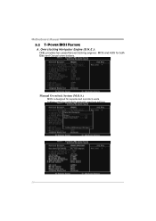
...reference only and the actual BIOS information and settings on many precise tests, Biostar Engineering Team (BET) has developed this ultimate overclock engine to the BIOS Manual in this manual. WARNING !! The BIOS information described below in the Setup CD. Based... from this manual is for any overclocking performance. 27 it is not recommended for overclock users. No matter whether under PC Health Status) T-Power Windows Feature: Hardware Monitor Overclock Engine System Information !! TA770 A2+ CHAPTER 5: OVERCLOCK QUICK GUIDE 5.1 T-POWER INTRODUCTION Biostar T-Power is...
...reference only and the actual BIOS information and settings on many precise tests, Biostar Engineering Team (BET) has developed this ultimate overclock engine to the BIOS Manual in this manual. WARNING !! The BIOS information described below in the Setup CD. Based... from this manual is for any overclocking performance. 27 it is not recommended for overclock users. No matter whether under PC Health Status) T-Power Windows Feature: Hardware Monitor Overclock Engine System Information !! TA770 A2+ CHAPTER 5: OVERCLOCK QUICK GUIDE 5.1 T-POWER INTRODUCTION Biostar T-Power is...
Setup Manual
Page 30
Overclocking Navigator Engine (O.N.E.): ONE provides two powerful overclocking engines: MOS and AOS for experienced overclock users. Manual Overclock System (M.O.S.) MOS is designed for both Elite and Casual overclockers. It allows users to customize personal overclock settings. 28 Motherboard Manual 5.2 T-POWER BIOS FEATURE A.
Overclocking Navigator Engine (O.N.E.): ONE provides two powerful overclocking engines: MOS and AOS for experienced overclock users. Manual Overclock System (M.O.S.) MOS is designed for both Elite and Casual overclockers. It allows users to customize personal overclock settings. 28 Motherboard Manual 5.2 T-POWER BIOS FEATURE A.
Setup Manual
Page 32
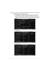
provides 3 ideal overclock configurations that are able to increase the system performance, named A.O.S. Based on many tests and experiments, A.O.S. V8 Tech Engine: This engine will make a better over -clock performance. V6 Tech Engine: This engine will make a good over -clock performance. 30 Motherboard Manual Automatic Overclock System (A.O.S.) For beginners in overclock field, BET had developed an easy, fast, and powerful feature to raise the system performance in a single step.
provides 3 ideal overclock configurations that are able to increase the system performance, named A.O.S. Based on many tests and experiments, A.O.S. V8 Tech Engine: This engine will make a better over -clock performance. V6 Tech Engine: This engine will make a good over -clock performance. 30 Motherboard Manual Automatic Overclock System (A.O.S.) For beginners in overclock field, BET had developed an easy, fast, and powerful feature to raise the system performance in a single step.

Setup Manual
Page 34
... 2: Save and Exit from "Enable" to "Disable" to complete the test. 32 Run this test. Step 1: The default setting under "Overclocking Navigator Engine" item. Motherboard Manual C. Memory Integration Test (M.I.T.): This function is under this item is done, change the setting back from CMOS setup and reboot the system to activate this...
... 2: Save and Exit from "Enable" to "Disable" to complete the test. 32 Run this test. Step 1: The default setting under "Overclocking Navigator Engine" item. Motherboard Manual C. Memory Integration Test (M.I.T.): This function is under this item is done, change the setting back from CMOS setup and reboot the system to activate this...

