Setup Manual
Page 2
Table of Contents Chapter 1: Introduction 1 1.1 Before You Start 1 1.2 Package Checklist 1 1.3 Motherboard Features 2 1.4 Rear Panel Connectors 3 1.5 Motherboard Layout 4 Chapter 2: Hardware Installation 5 2.1 Installing Central Processing Unit (CPU 5 2.2 FAN Headers 7 2.3 Installing System Memory 8 2.4 Connectors and Slots 10 Chapter 3: Headers & Jumpers Setup 12 3.1 How to ...
Table of Contents Chapter 1: Introduction 1 1.1 Before You Start 1 1.2 Package Checklist 1 1.3 Motherboard Features 2 1.4 Rear Panel Connectors 3 1.5 Motherboard Layout 4 Chapter 2: Hardware Installation 5 2.1 Installing Central Processing Unit (CPU 5 2.2 FAN Headers 7 2.3 Installing System Memory 8 2.4 Connectors and Slots 10 Chapter 3: Headers & Jumpers Setup 12 3.1 How to ...
Setup Manual
Page 3
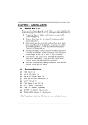
Before you start installing the motherboard, please make sure you follow the instructions below: „ Prepare a dry and stable working environment with sufficient lighting....not try to remove the static charge. „ Avoid touching the components on motherboard or the rear side of the board unless necessary. CHAPTER 1: INTRODUCTION TA780G M2+ 1.1 BEFORE YOU START Thank you take the motherboard out from dangerous area, such as heat source, humid air and water. ... equipment. „ Keep the computer from anti-static bag, ground yourself properly by area or your motherboard version. 1
Before you start installing the motherboard, please make sure you follow the instructions below: „ Prepare a dry and stable working environment with sufficient lighting....not try to remove the static charge. „ Avoid touching the components on motherboard or the rear side of the board unless necessary. CHAPTER 1: INTRODUCTION TA780G M2+ 1.1 BEFORE YOU START Thank you take the motherboard out from dangerous area, such as heat source, humid air and water. ... equipment. „ Keep the computer from anti-static bag, ground yourself properly by area or your motherboard version. 1

Setup Manual
Page 4
Motherboard Manual 1.3 MOTHERBOARD FEATURES SPEC Socket AM2+ / AM2 AMD 64 Architecture enables 32 and 64 bit CPU AMD Athlon 64 / Athlon 64 FX / Athlon 64 x2 computing / Sempron / ...
Motherboard Manual 1.3 MOTHERBOARD FEATURES SPEC Socket AM2+ / AM2 AMD 64 Architecture enables 32 and 64 bit CPU AMD Athlon 64 / Athlon 64 FX / Athlon 64 x2 computing / Sempron / ...
Setup Manual
Page 6
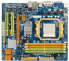
Motherboard Manual 1.5 MOTHERBOARD LAYOUT JKBMS1 JATXPWR2 JCFAN 1 JATXPWR1 Socket AM2+ DVI VGA DIMMA1 DIMMB1 DIMMA2 DIMMB2 JUSB1 JUSBLAN1 JUSBV1 JAUDIO1 JAUDIOF1 JCDIN1 LAN PE X1 _1 AMD 780G BAT TERY IDE1 Co dec PE X 16_ 1 Super I/O JCOM1 PCI1 JSPDI F_OUT1 PCI2 JPRNT1 FDD1 JSFAN1 JUSB4 AMD SB700 SATA5 SATA6 SATA3 JUSB3 JUSB2 SATA1 JCMOS1 JUSBV2 SATA2 JPANEL1 BIOS Note: ■ represents the 1st pin. 4 SATA4
Motherboard Manual 1.5 MOTHERBOARD LAYOUT JKBMS1 JATXPWR2 JCFAN 1 JATXPWR1 Socket AM2+ DVI VGA DIMMA1 DIMMB1 DIMMA2 DIMMB2 JUSB1 JUSBLAN1 JUSBV1 JAUDIO1 JAUDIOF1 JCDIN1 LAN PE X1 _1 AMD 780G BAT TERY IDE1 Co dec PE X 16_ 1 Super I/O JCOM1 PCI1 JSPDI F_OUT1 PCI2 JPRNT1 FDD1 JSFAN1 JUSB4 AMD SB700 SATA5 SATA6 SATA3 JUSB3 JUSB2 SATA1 JCMOS1 JUSBV2 SATA2 JPANEL1 BIOS Note: ■ represents the 1st pin. 4 SATA4

Setup Manual
Page 8
... the installation. In this case, please install one standard AM2 CPU to the JCFAN1. Step 5: Put the CPU Fan on the CPU and buckle it. Motherboard Manual Step 4: Hold the CPU down firmly, and then close the lever toward direct B to boot while using AM2+ CPUs.
... the installation. In this case, please install one standard AM2 CPU to the JCFAN1. Step 5: Put the CPU Fan on the CPU and buckle it. Motherboard Manual Step 4: Hold the CPU down firmly, and then close the lever toward direct B to boot while using AM2+ CPUs.
Setup Manual
Page 10
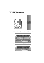
DIMMA1 DIMMB1 DIMMA2 DIMMB2 Motherboard Manual 2.3 INSTALLING SYSTEM MEMORY A. Align a DIMM on the slot such that the notch on the DIMM matches the break on the Slot. 2. Memory Modules 1. Unlock a DIMM slot by pressing the retaining clips outward. Insert the DIMM vertically and firmly into the slot until the retaining chip snap back in place and the DIMM is properly seated. 8
DIMMA1 DIMMB1 DIMMA2 DIMMB2 Motherboard Manual 2.3 INSTALLING SYSTEM MEMORY A. Align a DIMM on the slot such that the notch on the DIMM matches the break on the Slot. 2. Memory Modules 1. Unlock a DIMM slot by pressing the retaining clips outward. Insert the DIMM vertically and firmly into the slot until the retaining chip snap back in place and the DIMM is properly seated. 8
Setup Manual
Page 11
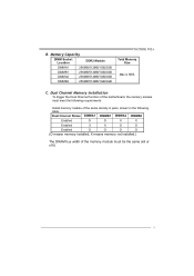
Dual Channel Memory installation To trigger the Dual Channel function of the motherboard, the memory module must meet the following requirements: Install memory module of the memory module must be the same (x8 or x16) 9 Dual Channel Status ... DIMM Socket Location DDR2 Module DIMMA1 256MB/512MB/1GB/2GB DIMMB1 256MB/512MB/1GB/2GB DIMMA2 256MB/512MB/1GB/2GB DIMMB2 256MB/512MB/1GB/2GB TA780G M2+ Total Memory Size Max is 8GB. C.
Dual Channel Memory installation To trigger the Dual Channel function of the motherboard, the memory module must meet the following requirements: Install memory module of the memory module must be the same (x8 or x16) 9 Dual Channel Status ... DIMM Socket Location DDR2 Module DIMMA1 256MB/512MB/1GB/2GB DIMMB1 256MB/512MB/1GB/2GB DIMMA2 256MB/512MB/1GB/2GB DIMMB2 256MB/512MB/1GB/2GB TA780G M2+ Total Memory Size Max is 8GB. C.
Setup Manual
Page 12
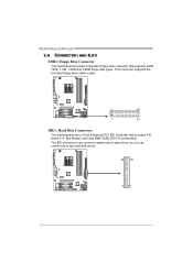
This connector supports the provided floppy drive ribbon cable. 2 34 1 33 IDE1: Hard Disk Connectors The motherboard has a 32-bit Enhanced PCI IDE Controller that supports 360K, 720K, 1.2M, 1.44M and 2.88M floppy disk types. Motherboard Manual 2.4 CONNECTORS AND SLOTS FDD1: Floppy Disk Connector The motherboard provides a standard floppy disk connector that provides PIO Mode 0~4, Bus Master, and Ultra DMA 33/66/100/133 functionality. The IDE connectors can connect a master and a slave drive, so you can connect up to two hard disk drives. 40 39 21 10
This connector supports the provided floppy drive ribbon cable. 2 34 1 33 IDE1: Hard Disk Connectors The motherboard has a 32-bit Enhanced PCI IDE Controller that supports 360K, 720K, 1.2M, 1.44M and 2.88M floppy disk types. Motherboard Manual 2.4 CONNECTORS AND SLOTS FDD1: Floppy Disk Connector The motherboard provides a standard floppy disk connector that provides PIO Mode 0~4, Bus Master, and Ultra DMA 33/66/100/133 functionality. The IDE connectors can connect a master and a slave drive, so you can connect up to two hard disk drives. 40 39 21 10
Setup Manual
Page 13
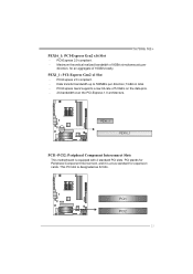
TA780G M2+ PEX16_1: PCI-Express Gen2 x16 Slot - PEX1_1: PCI-Express Gen2 x1 Slot - PCI-Express 2.0 compliant. - PEX1_1 PEX16_1 PCI1~PCI2: Peripheral Component Interconnect Slots This motherboard is designated as 32 bits. PCI1 PCI2 11 Data transfer bandwidth up to 500MB/s per direction, for expansion cards. This PCI slot is equipped with 2 ...
TA780G M2+ PEX16_1: PCI-Express Gen2 x16 Slot - PEX1_1: PCI-Express Gen2 x1 Slot - PCI-Express 2.0 compliant. - PEX1_1 PEX16_1 PCI1~PCI2: Peripheral Component Interconnect Slots This motherboard is designated as 32 bits. PCI1 PCI2 11 Data transfer bandwidth up to 500MB/s per direction, for expansion cards. This PCI slot is equipped with 2 ...
Setup Manual
Page 14
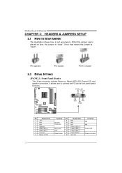
... LED Power-on pins, the jumper is "close", if not, that means the jumper is "open". When the jumper cap is placed on button 12 Motherboard Manual CHAPTER 3: HEADERS & JUMPERS SETUP 3.1 HOW TO SETUP JUMPERS The illustration shows how to connect the PC case's front panel switch functions. Pin opened Pin...
... LED Power-on pins, the jumper is "close", if not, that means the jumper is "open". When the jumper cap is placed on button 12 Motherboard Manual CHAPTER 3: HEADERS & JUMPERS SETUP 3.1 HOW TO SETUP JUMPERS The illustration shows how to connect the PC case's front panel switch functions. Pin opened Pin...

Setup Manual
Page 16
... JUSB3 JUSB2 2 10 19 Pin Assignment 1 +5V (fused) 2 +5V (fused) 3 USB4 USB5 USB+ 6 USB+ 7 Ground 8 Ground 9 NC 10 Key SATA1~SATA6: Serial ATA Connectors The motherboard has a PCI to connect additional USB cable on the PC front panel, and also can be connected with transfer rate of 3.0Gb.../s. Motherboard Manual JUSB2/JUSB3/JUSB4: Headers for USB 2.0 Ports at Front Panel This header allows user to SATA Controller with 6 channels SATA interface, it satisfies the ...
... JUSB3 JUSB2 2 10 19 Pin Assignment 1 +5V (fused) 2 +5V (fused) 3 USB4 USB5 USB+ 6 USB+ 7 Ground 8 Ground 9 NC 10 Key SATA1~SATA6: Serial ATA Connectors The motherboard has a PCI to connect additional USB cable on the PC front panel, and also can be connected with transfer rate of 3.0Gb.../s. Motherboard Manual JUSB2/JUSB3/JUSB4: Headers for USB 2.0 Ports at Front Panel This header allows user to SATA Controller with 6 channels SATA interface, it satisfies the ...
Setup Manual
Page 18
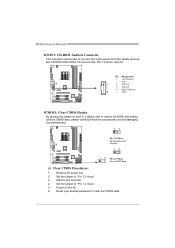
... seconds. 4. Remove AC power line. 2. Set the jumper to "Pin 1-2 close ". 3. Set the jumper to "Pin 2-3 close ". 5. Motherboard Manual JCDIN1: CD-ROM Audio-in Connector This connector allows user to avoid damaging the motherboard. 13 Pin 1-2 Close: Normal Operation (default). 13 13 Pin 2-3 Close: Clear CMOS data. ※ Clear CMOS Procedures: 1. Reset...
... seconds. 4. Remove AC power line. 2. Set the jumper to "Pin 1-2 close ". 3. Set the jumper to "Pin 2-3 close ". 5. Motherboard Manual JCDIN1: CD-ROM Audio-in Connector This connector allows user to avoid damaging the motherboard. 13 Pin 1-2 Close: Normal Operation (default). 13 13 Pin 2-3 Close: Clear CMOS data. ※ Clear CMOS Procedures: 1. Reset...
Setup Manual
Page 19
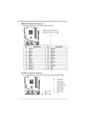
... 1 Carrier detect 2 Received data 3 Transmitted data 4 Data terminal ready 5 Signal ground 6 Data set ready 7 Request to send 2 10 8 Clear to connector printer on the PC. 2 1 TA780G M2+ 25 Pin Assignment 1 -Strobe 2 -ALF 3 Data 0 4 -Error 5 Data 1 6 -Init 7 Data 2 8 -Scltin 9 Data 3 10 Ground 11 Data 4 12 Ground 13 Data 5 Pin Assignment 14 Ground 15... 17 Data 7 18 Ground 19 -ACK 20 Ground 21 Busy 22 Ground 23 PE 24 Ground 25 SCLT 26 Key JCOM1: Serial port Connector The motherboard has a Serial Port Connector for connecting RS-232 Port.
... 1 Carrier detect 2 Received data 3 Transmitted data 4 Data terminal ready 5 Signal ground 6 Data set ready 7 Request to send 2 10 8 Clear to connector printer on the PC. 2 1 TA780G M2+ 25 Pin Assignment 1 -Strobe 2 -ALF 3 Data 0 4 -Error 5 Data 1 6 -Init 7 Data 2 8 -Scltin 9 Data 3 10 Ground 11 Data 4 12 Ground 13 Data 5 Pin Assignment 14 Ground 15... 17 Data 7 18 Ground 19 -ACK 20 Ground 21 Busy 22 Ground 23 PE 24 Ground 25 SCLT 26 Key JCOM1: Serial port Connector The motherboard has a Serial Port Connector for connecting RS-232 Port.
Setup Manual
Page 20
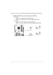
JUSBV2: +5V STB for USB ports at JUSB1/JUSBLAN1. JUSBV1 1 3 13 JUSBV2 13 1 3 Pin 1-2 close 13 1 3 Pin 2-3 close 18 Pin 2-3 Close: JUSBV1: +5V STB for USB ports at front panel (JUSB2/JUSB3/JUSB4). Motherboard Manual JUSBV1/JUSBV2: Power Source Headers for USB Ports Pin 1-2 Close: JUSBV1: +5V for USB ports at front panel (JUSB2/JUSB3/JUSB4). JUSBV2: +5V for USB ports at JUSB1/JUSBLAN1.
JUSBV2: +5V STB for USB ports at JUSB1/JUSBLAN1. JUSBV1 1 3 13 JUSBV2 13 1 3 Pin 1-2 close 13 1 3 Pin 2-3 close 18 Pin 2-3 Close: JUSBV1: +5V STB for USB ports at front panel (JUSB2/JUSB3/JUSB4). Motherboard Manual JUSBV1/JUSBV2: Power Source Headers for USB Ports Pin 1-2 Close: JUSBV1: +5V for USB ports at front panel (JUSB2/JUSB3/JUSB4). JUSBV2: +5V for USB ports at JUSB1/JUSBLAN1.
Setup Manual
Page 22
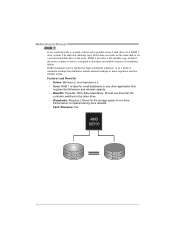
.... Uses: RAID 1 is actually carried out in parallel across 2 disk drives in the array. Drives: Minimum 2, and maximum is impaired during drive rebuilds. - Performance is 2. - Motherboard Manual RAID 1: Every read and write is ideal for small databases or any other drive. - The mirrored (backup) copy of the data can be applied...
.... Uses: RAID 1 is actually carried out in parallel across 2 disk drives in the array. Drives: Minimum 2, and maximum is impaired during drive rebuilds. - Performance is 2. - Motherboard Manual RAID 1: Every read and write is ideal for small databases or any other drive. - The mirrored (backup) copy of the data can be applied...

Setup Manual
Page 24
... Exit ESC Exit vxx.xx (C)Copyright 1985-200x, American Megatrends, Inc. 22 WARNING !! For further information of setting up the BIOS, please refer to malfunction. Motherboard Manual CHAPTER 5: T-SERIES BIOS & SOFTWARE 5.1 T-SERIES BIOS T-Series BIOS Features Overclocking Navigator Engine (O.N.E.) Memory Integration Test (M.I.T., under Overclock Navigator Engine) BIO-Flasher: Update BIOS file...
... Exit ESC Exit vxx.xx (C)Copyright 1985-200x, American Megatrends, Inc. 22 WARNING !! For further information of setting up the BIOS, please refer to malfunction. Motherboard Manual CHAPTER 5: T-SERIES BIOS & SOFTWARE 5.1 T-SERIES BIOS T-Series BIOS Features Overclocking Navigator Engine (O.N.E.) Memory Integration Test (M.I.T., under Overclock Navigator Engine) BIO-Flasher: Update BIOS file...
Setup Manual
Page 26
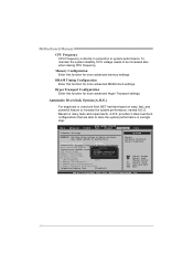
... beginners in a single step. Main Advanced PCIPnP BIOS SETUP UTILITY Boot Chipset T-Series Exit T-Series Settings WARNING: Setting wrong values in proportion to system performance. Motherboard Manual CPU Frequency CPU Frequency is directly in below sections may cause system to malfunction.
... beginners in a single step. Main Advanced PCIPnP BIOS SETUP UTILITY Boot Chipset T-Series Exit T-Series Settings WARNING: Setting wrong values in proportion to system performance. Motherboard Manual CPU Frequency CPU Frequency is directly in below sections may cause system to malfunction.
Setup Manual
Page 28
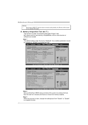
... types of AMD CPU perform above overclock setting ideally; MIT allows users to activate this test. the difference will be changed to "Enable" to malfunction. Motherboard Manual Notices: 1. the condition parameter should be based on the selected CPU model.
... types of AMD CPU perform above overclock setting ideally; MIT allows users to activate this test. the difference will be changed to "Enable" to malfunction. Motherboard Manual Notices: 1. the condition parameter should be based on the selected CPU model.
Setup Manual
Page 29
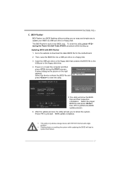
.... To enter the utility, press during the POST process. Select the proper BIOS file and press then to download the latest BIOS file for the motherboard. 2. A select dialog as the picture on or reset the computer and then press during the Power-On Self Tests (POST) procedure while booting up. Updating..., the utility will show the BIOS files and their respective information. z Shutting down or resetting the system while updating the BIOS will lead to proceed. TA780G M2+ C. Press to system boot failure. 27
.... To enter the utility, press during the POST process. Select the proper BIOS file and press then to download the latest BIOS file for the motherboard. 2. A select dialog as the picture on or reset the computer and then press during the Power-On Self Tests (POST) procedure while booting up. Updating..., the utility will show the BIOS files and their respective information. z Shutting down or resetting the system while updating the BIOS will lead to proceed. TA780G M2+ C. Press to system boot failure. 27
Setup Manual
Page 30
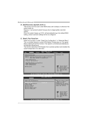
.../System Temperature vs. Fan speed. Change Option F1 General Help F10 Save and Exit ESC Exit vxx.xx (C)Copyright 1985-200x, American Megatrends, Inc. 28 Motherboard Manual D. and is a brilliant feature to define the Fan parameters for Smart Fan control Select Screen Select Item +- Smart Fan Function Smart Fan Function is...
.../System Temperature vs. Fan speed. Change Option F1 General Help F10 Save and Exit ESC Exit vxx.xx (C)Copyright 1985-200x, American Megatrends, Inc. 28 Motherboard Manual D. and is a brilliant feature to define the Fan parameters for Smart Fan control Select Screen Select Item +- Smart Fan Function Smart Fan Function is...

