
Setup Manual
Page 1
The content of this user's manual is subject to be changed without notice and we will not occur in a particular installation. This equipment generates, uses, and can radiate radio frequency energy ... the FCC Rules. There is no representations or warranties with respect to the contents here and specially disclaims any implied warranties of their respective companies. TA780G M2+ Setup Manual FCC Information and Copyright This equipment has been tested and found in this user...
The content of this user's manual is subject to be changed without notice and we will not occur in a particular installation. This equipment generates, uses, and can radiate radio frequency energy ... the FCC Rules. There is no representations or warranties with respect to the contents here and specially disclaims any implied warranties of their respective companies. TA780G M2+ Setup Manual FCC Information and Copyright This equipment has been tested and found in this user...
Setup Manual
Page 3
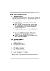
... HDD Cable X 1 Serial ATA Cable X 2 Serial ATA Power Cable X 1 Rear I/O Panel for choosing our product. CHAPTER 1: INTRODUCTION TA780G M2+ 1.1 BEFORE YOU START Thank you take the motherboard out from anti-static bag, ground yourself properly by area or your motherboard version. 1 ... and stable working environment with sufficient lighting. „ Always disconnect the computer from power outlet before operation. „ Before you for ATX Case X 1 User's Manual X 1 Fully Setup Driver CD X 1 FDD Cable X 1 (optional) USB 2.0 Cable X1 (optional) S/PDIF out Cable X 1 (optional) DVI to HDMI...
... HDD Cable X 1 Serial ATA Cable X 2 Serial ATA Power Cable X 1 Rear I/O Panel for choosing our product. CHAPTER 1: INTRODUCTION TA780G M2+ 1.1 BEFORE YOU START Thank you take the motherboard out from anti-static bag, ground yourself properly by area or your motherboard version. 1 ... and stable working environment with sufficient lighting. „ Always disconnect the computer from power outlet before operation. „ Before you for ATX Case X 1 User's Manual X 1 Fully Setup Driver CD X 1 FDD Cable X 1 (optional) USB 2.0 Cable X1 (optional) S/PDIF out Cable X 1 (optional) DVI to HDMI...

Setup Manual
Page 4
Motherboard Manual 1.3 MOTHERBOARD FEATURES SPEC Socket AM2+ / AM2 AMD 64 Architecture enables 32 and 64 bit CPU AMD Athlon 64 / Athlon 64 FX / Athlon 64 x2 computing / ...
Motherboard Manual 1.3 MOTHERBOARD FEATURES SPEC Socket AM2+ / AM2 AMD 64 Architecture enables 32 and 64 bit CPU AMD Athlon 64 / Athlon 64 FX / Athlon 64 x2 computing / ...
Setup Manual
Page 6
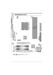
Motherboard Manual 1.5 MOTHERBOARD LAYOUT JKBMS1 JATXPWR2 JCFAN 1 JATXPWR1 Socket AM2+ DVI VGA DIMMA1 DIMMB1 DIMMA2 DIMMB2 JUSB1 JUSBLAN1 JUSBV1 JAUDIO1 JAUDIOF1 JCDIN1 LAN PE X1 _1 AMD 780G BAT TERY IDE1 Co dec PE X 16_ 1 Super I/O JCOM1 PCI1 JSPDI F_OUT1 PCI2 JPRNT1 FDD1 JSFAN1 JUSB4 AMD SB700 SATA5 SATA6 SATA3 JUSB3 JUSB2 SATA1 JCMOS1 JUSBV2 SATA2 JPANEL1 BIOS Note: ■ represents the 1st pin. 4 SATA4
Motherboard Manual 1.5 MOTHERBOARD LAYOUT JKBMS1 JATXPWR2 JCFAN 1 JATXPWR1 Socket AM2+ DVI VGA DIMMA1 DIMMB1 DIMMA2 DIMMB2 JUSB1 JUSBLAN1 JUSBV1 JAUDIO1 JAUDIOF1 JCDIN1 LAN PE X1 _1 AMD 780G BAT TERY IDE1 Co dec PE X 16_ 1 Super I/O JCOM1 PCI1 JSPDI F_OUT1 PCI2 JPRNT1 FDD1 JSFAN1 JUSB4 AMD SB700 SATA5 SATA6 SATA3 JUSB3 JUSB2 SATA1 JCMOS1 JUSBV2 SATA2 JPANEL1 BIOS Note: ■ represents the 1st pin. 4 SATA4

Setup Manual
Page 8
Note: Please update the BIOS to the latest version while using new AM2+ CPUs. This completes the installation. Motherboard Manual Step 4: Hold the CPU down firmly, and then close the lever toward direct B to boot your system, and update the latest BIOS from our website ...
Note: Please update the BIOS to the latest version while using new AM2+ CPUs. This completes the installation. Motherboard Manual Step 4: Hold the CPU down firmly, and then close the lever toward direct B to boot your system, and update the latest BIOS from our website ...
Setup Manual
Page 10
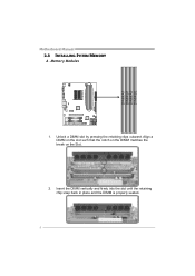
Insert the DIMM vertically and firmly into the slot until the retaining chip snap back in place and the DIMM is properly seated. 8 Align a DIMM on the slot such that the notch on the DIMM matches the break on the Slot. 2. Memory Modules 1. Unlock a DIMM slot by pressing the retaining clips outward. DIMMA1 DIMMB1 DIMMA2 DIMMB2 Motherboard Manual 2.3 INSTALLING SYSTEM MEMORY A.
Insert the DIMM vertically and firmly into the slot until the retaining chip snap back in place and the DIMM is properly seated. 8 Align a DIMM on the slot such that the notch on the DIMM matches the break on the Slot. 2. Memory Modules 1. Unlock a DIMM slot by pressing the retaining clips outward. DIMMA1 DIMMB1 DIMMA2 DIMMB2 Motherboard Manual 2.3 INSTALLING SYSTEM MEMORY A.
Setup Manual
Page 12
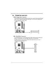
Motherboard Manual 2.4 CONNECTORS AND SLOTS FDD1: Floppy Disk Connector The motherboard provides a standard floppy disk connector that provides PIO Mode 0~4, Bus Master, and Ultra DMA 33/66/100/133 functionality. The IDE connectors can connect a master and a slave drive, so you can connect up to two hard disk drives. 40 39 21 10 This connector supports the provided floppy drive ribbon cable. 2 34 1 33 IDE1: Hard Disk Connectors The motherboard has a 32-bit Enhanced PCI IDE Controller that supports 360K, 720K, 1.2M, 1.44M and 2.88M floppy disk types.
Motherboard Manual 2.4 CONNECTORS AND SLOTS FDD1: Floppy Disk Connector The motherboard provides a standard floppy disk connector that provides PIO Mode 0~4, Bus Master, and Ultra DMA 33/66/100/133 functionality. The IDE connectors can connect a master and a slave drive, so you can connect up to two hard disk drives. 40 39 21 10 This connector supports the provided floppy drive ribbon cable. 2 34 1 33 IDE1: Hard Disk Connectors The motherboard has a 32-bit Enhanced PCI IDE Controller that supports 360K, 720K, 1.2M, 1.44M and 2.88M floppy disk types.
Setup Manual
Page 14
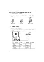
... LED (+) Power LED (-) Power button Ground Function N/A N/A Power LED Power-on pins, the jumper is "close", if not, that means the jumper is "open". Motherboard Manual CHAPTER 3: HEADERS & JUMPERS SETUP 3.1 HOW TO SETUP JUMPERS The illustration shows how to connect the PC case's front panel switch functions. It allows user to...
... LED (+) Power LED (-) Power button Ground Function N/A N/A Power LED Power-on pins, the jumper is "close", if not, that means the jumper is "open". Motherboard Manual CHAPTER 3: HEADERS & JUMPERS SETUP 3.1 HOW TO SETUP JUMPERS The illustration shows how to connect the PC case's front panel switch functions. It allows user to...

Setup Manual
Page 16
... The motherboard has a PCI to connect additional USB cable on the PC front panel, and also can be connected with transfer rate of 3.0Gb/s. Motherboard Manual JUSB2/JUSB3/JUSB4: Headers for USB 2.0 Ports at Front Panel This header allows user to SATA Controller with 6 channels SATA interface, it satisfies the SATA...
... The motherboard has a PCI to connect additional USB cable on the PC front panel, and also can be connected with transfer rate of 3.0Gb/s. Motherboard Manual JUSB2/JUSB3/JUSB4: Headers for USB 2.0 Ports at Front Panel This header allows user to SATA Controller with 6 channels SATA interface, it satisfies the SATA...
Setup Manual
Page 18
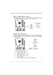
... for five seconds. 4. Pin Assignment 1 Left Channel Input 1 2 Ground 3 Ground 4 Right Channel 4 Input JCMOS1: Clear CMOS Header By placing the jumper on the AC. 6. Motherboard Manual JCDIN1: CD-ROM Audio-in Connector This connector allows user to avoid damaging the motherboard. 13 Pin 1-2 Close: Normal Operation (default). 13 13 Pin 2-3 Close...
... for five seconds. 4. Pin Assignment 1 Left Channel Input 1 2 Ground 3 Ground 4 Right Channel 4 Input JCMOS1: Clear CMOS Header By placing the jumper on the AC. 6. Motherboard Manual JCDIN1: CD-ROM Audio-in Connector This connector allows user to avoid damaging the motherboard. 13 Pin 1-2 Close: Normal Operation (default). 13 13 Pin 2-3 Close...
Setup Manual
Page 20
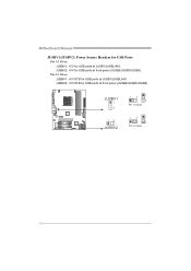
JUSBV2: +5V STB for USB ports at JUSB1/JUSBLAN1. JUSBV1 1 3 13 JUSBV2 13 1 3 Pin 1-2 close 13 1 3 Pin 2-3 close 18 Pin 2-3 Close: JUSBV1: +5V STB for USB ports at front panel (JUSB2/JUSB3/JUSB4). JUSBV2: +5V for USB ports at JUSB1/JUSBLAN1. Motherboard Manual JUSBV1/JUSBV2: Power Source Headers for USB Ports Pin 1-2 Close: JUSBV1: +5V for USB ports at front panel (JUSB2/JUSB3/JUSB4).
JUSBV2: +5V STB for USB ports at JUSB1/JUSBLAN1. JUSBV1 1 3 13 JUSBV2 13 1 3 Pin 1-2 close 13 1 3 Pin 2-3 close 18 Pin 2-3 Close: JUSBV1: +5V STB for USB ports at front panel (JUSB2/JUSB3/JUSB4). JUSBV2: +5V for USB ports at JUSB1/JUSBLAN1. Motherboard Manual JUSBV1/JUSBV2: Power Source Headers for USB Ports Pin 1-2 Close: JUSBV1: +5V for USB ports at front panel (JUSB2/JUSB3/JUSB4).
Setup Manual
Page 22
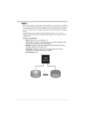
Motherboard Manual RAID 1: Every read and write is actually carried out in parallel across 2 disk drives in the array. The mirrored (backup) copy of one drive fail, ... Tolerance: Yes. Drives: Minimum 2, and maximum is impaired during drive rebuilds. - Uses: RAID 1 is corrupted or becomes unavailable because of automatic backup that eliminates tedious manual backups to the other application that requires fault tolerance and minimal capacity. - Performance is 2. - Should one drive. Block 1 Block 2 Block 3 Block 1 Block 2 Block 3 20...
Motherboard Manual RAID 1: Every read and write is actually carried out in parallel across 2 disk drives in the array. The mirrored (backup) copy of one drive fail, ... Tolerance: Yes. Drives: Minimum 2, and maximum is impaired during drive rebuilds. - Uses: RAID 1 is corrupted or becomes unavailable because of automatic backup that eliminates tedious manual backups to the other application that requires fault tolerance and minimal capacity. - Performance is 2. - Should one drive. Block 1 Block 2 Block 3 Block 1 Block 2 Block 3 20...

Setup Manual
Page 24
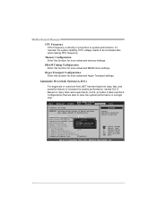
... refer to malfunction. OverClock Navigator [Normal] =========== Automate OverClock System =========== Auto OverClock System [V6-Tech Engine] Manual OverClock System CPU Overvoltage [StartUp] Memory Overvoltage [1.95V] Chipset Overvoltage [1.15V] HT Overvoltage [1.20V] CPU Frequency...Configuration > DRAM Timing Configuration > Hyper Transport Configuration Integrated Memory Test [Disabled] Options Normal Automate OverClock Manual OverClock Select Screen Select Item +- Overclocking Navigator Engine (O.N.E.) ONE provides two powerful overclocking engines: MOS and...
... refer to malfunction. OverClock Navigator [Normal] =========== Automate OverClock System =========== Auto OverClock System [V6-Tech Engine] Manual OverClock System CPU Overvoltage [StartUp] Memory Overvoltage [1.95V] Chipset Overvoltage [1.15V] HT Overvoltage [1.20V] CPU Frequency...Configuration > DRAM Timing Configuration > Hyper Transport Configuration Integrated Memory Test [Disabled] Options Normal Automate OverClock Manual OverClock Select Screen Select Item +- Overclocking Navigator Engine (O.N.E.) ONE provides two powerful overclocking engines: MOS and...

Setup Manual
Page 25
...is designed for experienced overclock users. OverClock Navigator [Normal] =========== Automate OverClock System =========== Auto OverClock System [V6-TOepcthionEsngine] Manual OverClockNoSrymsatlem CPU Overvoltage Au[SttoamrattUep]OverClock Memory Overvoltage Ma[1n.u9a5lV]OverClock Chipset Overvoltage [1.15V] HT Overvoltage [1.20V] CPU ...Megatrends, Inc. It allows users to customize personal overclock settings. TA780G M2+ Manual Overclock System (M.O.S.) MOS is increased. CPU Overvoltage This function will increase Northbridge and Southbridge chipset stability when overclocking...
...is designed for experienced overclock users. OverClock Navigator [Normal] =========== Automate OverClock System =========== Auto OverClock System [V6-TOepcthionEsngine] Manual OverClockNoSrymsatlem CPU Overvoltage Au[SttoamrattUep]OverClock Memory Overvoltage Ma[1n.u9a5lV]OverClock Chipset Overvoltage [1.15V] HT Overvoltage [1.20V] CPU ...Megatrends, Inc. It allows users to customize personal overclock settings. TA780G M2+ Manual Overclock System (M.O.S.) MOS is increased. CPU Overvoltage This function will increase Northbridge and Southbridge chipset stability when overclocking...
Setup Manual
Page 26
...tests and experiments, A.O.S. OverClock Navigator [Normal] =========== Automate OverClock System =========== Auto OverClock System [V6-TOepcthionEsngine] Manual OverClockNoSrymsatlem CPU Overvoltage Au[SttoamrattUep]OverClock Memory Overvoltage Ma[1n.u9a5lV]OverClock Chipset Overvoltage [1.15V] HT Overvoltage [1.20V...Configuration > Hyper Transport Configuration Integrated Memory Test [Disabled] Options Normal Automate OverClock Manual OverClock Select Screen Select Item +- Motherboard Manual CPU Frequency CPU Frequency is directly in overclock field, BET had developed an ...
...tests and experiments, A.O.S. OverClock Navigator [Normal] =========== Automate OverClock System =========== Auto OverClock System [V6-TOepcthionEsngine] Manual OverClockNoSrymsatlem CPU Overvoltage Au[SttoamrattUep]OverClock Memory Overvoltage Ma[1n.u9a5lV]OverClock Chipset Overvoltage [1.15V] HT Overvoltage [1.20V...Configuration > Hyper Transport Configuration Integrated Memory Test [Disabled] Options Normal Automate OverClock Manual OverClock Select Screen Select Item +- Motherboard Manual CPU Frequency CPU Frequency is directly in overclock field, BET had developed an ...

Setup Manual
Page 27
... a good over-clock performance. OverClock Navigator [Automate OverClock] =========== Automate OverClock System =========== Auto OverClock System [V12-Tech Engine] Manual OverClock System CPU Overvoltage [StartUp] Memory Overvoltage [1.95V] Chipset Overvoltage [1.15V] HT Overvoltage [1.20V] CPU Frequency [200] ...] Options Normal Automate OverClock Manual OverClock Select Screen Select Item +- V6 Tech Engine This engine will make a best over-clock performance. Main Advanced PCIPnP BIOS SETUP UTILITY Boot Chipset T-Series TA780G M2+ Exit T-Series Settings WARNING...
... a good over-clock performance. OverClock Navigator [Automate OverClock] =========== Automate OverClock System =========== Auto OverClock System [V12-Tech Engine] Manual OverClock System CPU Overvoltage [StartUp] Memory Overvoltage [1.95V] Chipset Overvoltage [1.15V] HT Overvoltage [1.20V] CPU Frequency [200] ...] Options Normal Automate OverClock Manual OverClock Select Screen Select Item +- V6 Tech Engine This engine will make a best over-clock performance. Main Advanced PCIPnP BIOS SETUP UTILITY Boot Chipset T-Series TA780G M2+ Exit T-Series Settings WARNING...
Setup Manual
Page 28
...allows users to malfunction. OverClock Navigator [Normal] =========== Automate OverClock System =========== Auto OverClock System [V6-Tech Engine] Manual OverClock System CPU Overvoltage [StartUp] Memory Overvoltage [1.95V] Chipset Overvoltage [1.15V] HT Overvoltage [1.20V] CPU Frequency...software are needed. OverClock Navigator [Normal] =========== Automate OverClock System =========== Auto OverClock System [V6-Tech Engine] Manual OverClock System CPU Overvoltage [StartUp] Memory Overvoltage [1.95V] Chipset Overvoltage [1.15V] HT Overvoltage [1.20V] CPU ...
...allows users to malfunction. OverClock Navigator [Normal] =========== Automate OverClock System =========== Auto OverClock System [V6-Tech Engine] Manual OverClock System CPU Overvoltage [StartUp] Memory Overvoltage [1.95V] Chipset Overvoltage [1.15V] HT Overvoltage [1.20V] CPU Frequency...software are needed. OverClock Navigator [Normal] =========== Automate OverClock System =========== Auto OverClock System [V6-Tech Engine] Manual OverClock System CPU Overvoltage [StartUp] Memory Overvoltage [1.95V] Chipset Overvoltage [1.15V] HT Overvoltage [1.20V] CPU ...
Setup Manual
Page 30
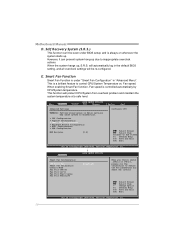
... Option F1 General Help F10 Save and Exit ESC Exit vxx.xx (C)Copyright 1985-200x, American Megatrends, Inc. 28 When the system hangs up . Motherboard Manual D. and is a brilliant feature to malfunction. > CPU Configuration > SuperIO Configuration > Smart Fan Configuration > Hardware Health Configuration > ACPI Configuration > USB Configuration MPS Revision [1.4] Configure CPU...
... Option F1 General Help F10 Save and Exit ESC Exit vxx.xx (C)Copyright 1985-200x, American Megatrends, Inc. 28 When the system hangs up . Motherboard Manual D. and is a brilliant feature to malfunction. > CPU Configuration > SuperIO Configuration > Smart Fan Configuration > Hardware Health Configuration > ACPI Configuration > USB Configuration MPS Revision [1.4] Configure CPU...
Setup Manual
Page 32
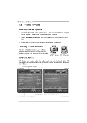
... f an speed Turn to maintain the health of CPU/GPU/System temperature, fan speed, and voltage. Double-click the icon to launch T-Series utility. Motherboard Manual 5.2 T-SERIES SOFTWARE Installing T-Series Software 1. It provides real-time information of the PC.
... f an speed Turn to maintain the health of CPU/GPU/System temperature, fan speed, and voltage. Double-click the icon to launch T-Series utility. Motherboard Manual 5.2 T-SERIES SOFTWARE Installing T-Series Software 1. It provides real-time information of the PC.
Setup Manual
Page 34
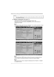
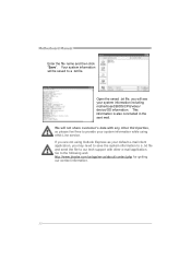
... parties, so please feel free to provide your default e-mail client application, you will be saved to the following web http://www.biostar.com.tw/app/en-us/about/contact.php for getting our contact information. 32 Your system information will see your system information including ...motherboard/BIOS/CPU/video/ device/OS information. Motherboard Manual Enter the file name and then click "Save". Open the saved .txt file, you may need to save the system information to a ...
... parties, so please feel free to provide your default e-mail client application, you will be saved to the following web http://www.biostar.com.tw/app/en-us/about/contact.php for getting our contact information. 32 Your system information will see your system information including ...motherboard/BIOS/CPU/video/ device/OS information. Motherboard Manual Enter the file name and then click "Save". Open the saved .txt file, you may need to save the system information to a ...

