
Bios Setup
Page 21
...option will let user know boot success with beep. Options: ON (Default) / OFF Interrupt 19 Capture When set to Enabled, BIOS would ignore memory error messages. The number of device items that appears on the screen depends on . Master / Pri. Options: Force BIOS (Default) / Keep ... the CD/DVD drive boot sequence automatically. TA790GX A3+ BIOS Manual CD/DV D Drives T he BIOS will attempt to trap interrupt 19. You can also change the booting sequence. Slave / Sec. Master / Sec. Options: Enabled (Default) / Disabled Ignore Memory Error Messages When set to Enabled, this item ...
...option will let user know boot success with beep. Options: ON (Default) / OFF Interrupt 19 Capture When set to Enabled, BIOS would ignore memory error messages. The number of device items that appears on the screen depends on . Master / Pri. Options: Force BIOS (Default) / Keep ... the CD/DVD drive boot sequence automatically. TA790GX A3+ BIOS Manual CD/DV D Drives T he BIOS will attempt to trap interrupt 19. You can also change the booting sequence. Slave / Sec. Master / Sec. Options: Enabled (Default) / Disabled Ignore Memory Error Messages When set to Enabled, this item ...

Setup Manual
Page 20
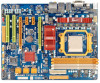
Motherboard Manual On-Board LED Indicators There are 2 on-board buttons. RSTSW1: Reset button. 18 PHASE1_LED~PHASE4_LED ON OFF Phase Indicator Phase Active Phase Disable On-Board Buttons There are 6 LED indicators showing system status. PHASE1_LED PHASE2_LED PHASE3_LED PHASE4_LED LED_D2 LED_D1 LED1 & LED2: Debug Indicators PH1 ~ PH4: Power Status Indicators Please refer to the tables below for specific messages: LED1 LED2 Message ON ON Normal ON OFF Memory Error OFF ON VGA Error OFF OFF Abnormal: CPU / Chipset error. PWRSW1 RSTSW1 PWRSW1: Power Switch button.
Motherboard Manual On-Board LED Indicators There are 2 on-board buttons. RSTSW1: Reset button. 18 PHASE1_LED~PHASE4_LED ON OFF Phase Indicator Phase Active Phase Disable On-Board Buttons There are 6 LED indicators showing system status. PHASE1_LED PHASE2_LED PHASE3_LED PHASE4_LED LED_D2 LED_D1 LED1 & LED2: Debug Indicators PH1 ~ PH4: Power Status Indicators Please refer to the tables below for specific messages: LED1 LED2 Message ON ON Normal ON OFF Memory Error OFF ON VGA Error OFF OFF Abnormal: CPU / Chipset error. PWRSW1 RSTSW1 PWRSW1: Power Switch button.

Setup Manual
Page 48
... layout does not match image present in flash device) POST BIOS Beep Codes Number of Beeps Description 1 Memory refresh timer error 3 Base memory read/write test error 6 Keyboard controller BAT command failed 7 General exception error (processor exception interrupt error) 8 Display memory error (system video adapter) Troubleshooting POST BIOS Beep Codes Number of interference by a malfunctioning add-in card...
... layout does not match image present in flash device) POST BIOS Beep Codes Number of Beeps Description 1 Memory refresh timer error 3 Base memory read/write test error 6 Keyboard controller BAT command failed 7 General exception error (processor exception interrupt error) 8 Display memory error (system video adapter) Troubleshooting POST BIOS Beep Codes Number of interference by a malfunctioning add-in card...


