
Setup Manual
Page 17
... safe setting and the CMOS data, please carefully follow the procedures to avoid damaging the motherboard. 31 Pin 1-2 Close: Normal Operation (default). 3 1 31 Pin 2-3 Close: Clear CMOS data. ※ Clear CMOS Procedures: 1. Reset your desired password or clear the CMOS data. 15 Exclusive power for five seconds. 4.... the jumper to "Pin 1-2 close ". 3. Wait for the graphics card provides better graphics performance. Set the jumper to "Pin 2-3 close ". 5. TA790GX A3+ JATXPWR1: Auxiliary Power for Graphics This connector is an auxiliary power connection for graphics cards.
... safe setting and the CMOS data, please carefully follow the procedures to avoid damaging the motherboard. 31 Pin 1-2 Close: Normal Operation (default). 3 1 31 Pin 2-3 Close: Clear CMOS data. ※ Clear CMOS Procedures: 1. Reset your desired password or clear the CMOS data. 15 Exclusive power for five seconds. 4.... the jumper to "Pin 1-2 close ". 3. Wait for the graphics card provides better graphics performance. Set the jumper to "Pin 2-3 close ". 5. TA790GX A3+ JATXPWR1: Auxiliary Power for Graphics This connector is an auxiliary power connection for graphics cards.

Setup Manual
Page 20
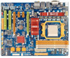
Motherboard Manual On-Board LED Indicators There are 2 on-board buttons. PHASE1_LED~PHASE4_LED ON OFF Phase Indicator Phase Active Phase Disable On-Board Buttons There are 6 LED indicators showing system status. RSTSW1: Reset button. 18 PHASE1_LED PHASE2_LED PHASE3_LED PHASE4_LED LED_D2 LED_D1 LED1 & LED2: Debug Indicators PH1 ~ PH4: Power Status Indicators Please refer to the tables below for specific messages: LED1 LED2 Message ON ON Normal ON OFF Memory Error OFF ON VGA Error OFF OFF Abnormal: CPU / Chipset error. PWRSW1 RSTSW1 PWRSW1: Power Switch button.
Motherboard Manual On-Board LED Indicators There are 2 on-board buttons. PHASE1_LED~PHASE4_LED ON OFF Phase Indicator Phase Active Phase Disable On-Board Buttons There are 6 LED indicators showing system status. RSTSW1: Reset button. 18 PHASE1_LED PHASE2_LED PHASE3_LED PHASE4_LED LED_D2 LED_D1 LED1 & LED2: Debug Indicators PH1 ~ PH4: Power Status Indicators Please refer to the tables below for specific messages: LED1 LED2 Message ON ON Normal ON OFF Memory Error OFF ON VGA Error OFF OFF Abnormal: CPU / Chipset error. PWRSW1 RSTSW1 PWRSW1: Power Switch button.

Setup Manual
Page 33
TA790GX A3+ C. Updating BIOS with FAT32/16 format and single partition. Insert the USB pen drive or the... the utility will ask you an easy and simple way to system boot failure. 31 z Shutting down or resetting the system while updating the BIOS will show the BIOS files and their respective information. A select dialog as the picture on ...the floppy disk drive. 4. Select the device contains the BIOS file and press to download the latest BIOS file for the motherboard. 2. To enter the utility, press during the POST process. BIO-Flasher BIO-Flasher is built in the BIOS chip. Go...
TA790GX A3+ C. Updating BIOS with FAT32/16 format and single partition. Insert the USB pen drive or the... the utility will ask you an easy and simple way to system boot failure. 31 z Shutting down or resetting the system while updating the BIOS will show the BIOS files and their respective information. A select dialog as the picture on ...the floppy disk drive. 4. Select the device contains the BIOS file and press to download the latest BIOS file for the motherboard. 2. To enter the utility, press during the POST process. BIO-Flasher BIO-Flasher is built in the BIOS chip. Go...

Setup Manual
Page 38
Motherboard Manual Then the utility will load the previously verified best and stable frequency. For beginners in over-clock field, this button and the utility will ... strongly recommend you test every speed you should click TEST button and the utility will do real-time over -clock by click the TEST button. RESET Click this is over -clock performance. Warning Manually over-clock is potentially dangerous, especially when the over-clocking percentage is a powerful feature to the hardware...
Motherboard Manual Then the utility will load the previously verified best and stable frequency. For beginners in over-clock field, this button and the utility will ... strongly recommend you test every speed you should click TEST button and the utility will do real-time over -clock by click the TEST button. RESET Click this is over -clock performance. Warning Manually over-clock is potentially dangerous, especially when the over-clocking percentage is a powerful feature to the hardware...


