
Setup Manual
Page 2
Table of Contents Chapter 1: Introduction 1 1.1 Before You Start 1 1.2 Package Checklist 1 1.3 Motherboard Features 2 1.4 Rear Panel Connectors 3 1.5 Motherboard Layout 4 Chapter 2: Hardware Installation 5 2.1 Installing Central Processing Unit (CPU 5 2.2 FAN Headers 7 2.3 Installing System Memory 8 2.4 Connectors and Slots 10 Chapter 3: Headers & Jumpers Setup 13 3.1 How to ...
Table of Contents Chapter 1: Introduction 1 1.1 Before You Start 1 1.2 Package Checklist 1 1.3 Motherboard Features 2 1.4 Rear Panel Connectors 3 1.5 Motherboard Layout 4 Chapter 2: Hardware Installation 5 2.1 Installing Central Processing Unit (CPU 5 2.2 FAN Headers 7 2.3 Installing System Memory 8 2.4 Connectors and Slots 10 Chapter 3: Headers & Jumpers Setup 13 3.1 How to ...

Setup Manual
Page 3
...heat source, humid air and water. „ The operating temperatures of the board unless necessary. CHAPTER 1: INTRODUCTION TA990FXE 1.1 BEFORE YOU START Thank you take the motherboard out from anti-static bag, ground yourself properly by touching any unfastened small parts inside the case after installation. ...flex the board. „ Do not leave any safely grounded appliance, or use grounded wrist strap to area or your motherboard version. 1 Hold the board on motherboard or the rear side of the computer should be 0 to 45 degrees Celsius. 1.2 PACKAGE CHECKLIST Serial ATA Cable X4...
...heat source, humid air and water. „ The operating temperatures of the board unless necessary. CHAPTER 1: INTRODUCTION TA990FXE 1.1 BEFORE YOU START Thank you take the motherboard out from anti-static bag, ground yourself properly by touching any unfastened small parts inside the case after installation. ...flex the board. „ Do not leave any safely grounded appliance, or use grounded wrist strap to area or your motherboard version. 1 Hold the board on motherboard or the rear side of the computer should be 0 to 45 degrees Celsius. 1.2 PACKAGE CHECKLIST Serial ATA Cable X4...

Setup Manual
Page 4
... up to factory default USB2.0 Connector x2 Each connector supports 2 front panel USB2.0 ports 2 SATA III Integrated Serial ATA Controller SATA Version 3.0 specification compliant. Motherboard Manual 1.3 MOTHERBOARD FEATURES SPEC Socket AM3+ AMD 64 Architecture enables 32 and 64 bit CPU AMD Sempron / Phenom II / Athlon II / FX computing processors Supports Hyper Transport...
... up to factory default USB2.0 Connector x2 Each connector supports 2 front panel USB2.0 ports 2 SATA III Integrated Serial ATA Controller SATA Version 3.0 specification compliant. Motherboard Manual 1.3 MOTHERBOARD FEATURES SPEC Socket AM3+ AMD 64 Architecture enables 32 and 64 bit CPU AMD Sempron / Phenom II / Athlon II / FX computing processors Supports Hyper Transport...

Setup Manual
Page 6
NB_PH_ LE D PH1_ D1 PH3_ D3 PH2_ D2 PH4_ D4 Motherboard Manual 1.5 MOTHERBOARD LAYOUT KB MS1 CP U_FA N1 S PDI F1 ATXP WR2 U SB1 Socke t AM 3+ USB _1394_ ES ATA 1 RJ45USB 1 JUS BV 1 DD R3_A1 DD R3_A2 DD R3_B1 DD R3_B2 ATXP WR1 AUDIO1 LAN Codec A UXP WR1 SY S_FA N2 PEX16_1 AMD 990FX PEX1_1 PEX16_2 PEX16_3 PCI1 JC MOS1 BAT1 AMD SB950 SATA 2 BIOS SATA 1 SATA3 Super I/O F_AU DIO1 C IR1 PCI2 J_COM1 JSP DI FOUT1 S YS _FAN1 F_1394A 1 JFRONT_US B3_1 F_U SB1 JUSBV2 SW_PWR1 F_USB2 SW_RST1 PAN EL1 Note: ■ represents the 1st pin. 4
NB_PH_ LE D PH1_ D1 PH3_ D3 PH2_ D2 PH4_ D4 Motherboard Manual 1.5 MOTHERBOARD LAYOUT KB MS1 CP U_FA N1 S PDI F1 ATXP WR2 U SB1 Socke t AM 3+ USB _1394_ ES ATA 1 RJ45USB 1 JUS BV 1 DD R3_A1 DD R3_A2 DD R3_B1 DD R3_B2 ATXP WR1 AUDIO1 LAN Codec A UXP WR1 SY S_FA N2 PEX16_1 AMD 990FX PEX1_1 PEX16_2 PEX16_3 PCI1 JC MOS1 BAT1 AMD SB950 SATA 2 BIOS SATA 1 SATA3 Super I/O F_AU DIO1 C IR1 PCI2 J_COM1 JSP DI FOUT1 S YS _FAN1 F_1394A 1 JFRONT_US B3_1 F_U SB1 JUSBV2 SW_PWR1 F_USB2 SW_RST1 PAN EL1 Note: ■ represents the 1st pin. 4

Setup Manual
Page 8
Step 4: Put the CPU Fan on the CPU and buckle it. This completes the installation. 6 Motherboard Manual Step 3: Hold the CPU down firmly, and then close the lever toward direct B to the CPU_FAN1. Connect the CPU FAN power cable to complete the installation.
Step 4: Put the CPU Fan on the CPU and buckle it. This completes the installation. 6 Motherboard Manual Step 3: Hold the CPU down firmly, and then close the lever toward direct B to the CPU_FAN1. Connect the CPU FAN power cable to complete the installation.
Setup Manual
Page 10
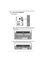
Insert the DIMM vertically and firmly into the slot until the retaining chip snap back in place and the DIMM is properly seated. 8 DDR 3_A1 DDR 3_A2 DDR 3_B1 DDR 3_B2 Motherboard Manual 2.3 INSTALLING SYSTEM MEMORY A. Align a DIMM on the slot such that the notch on the DIMM matches the break on the Slot. 2. Unlock a DIMM slot by pressing the retaining clips outward. DDR3 Modules 1.
Insert the DIMM vertically and firmly into the slot until the retaining chip snap back in place and the DIMM is properly seated. 8 DDR 3_A1 DDR 3_A2 DDR 3_B1 DDR 3_B2 Motherboard Manual 2.3 INSTALLING SYSTEM MEMORY A. Align a DIMM on the slot such that the notch on the DIMM matches the break on the Slot. 2. Unlock a DIMM slot by pressing the retaining clips outward. DDR3 Modules 1.

Setup Manual
Page 12
... 4 1 1 +12V 2 Ground 3 Ground 4 VCC ATXPWR2: ATX Power Source Connector This connector provides +12V to SATA Controller with 5 channels SATA interface, it into Pin 1-2-7-8 of 6.0Gb/s. Motherboard Manual 2.4 CONNECTORS AND SLOTS SATA1~SATA3: Serial ATA Connectors The...
... 4 1 1 +12V 2 Ground 3 Ground 4 VCC ATXPWR2: ATX Power Source Connector This connector provides +12V to SATA Controller with 5 channels SATA interface, it into Pin 1-2-7-8 of 6.0Gb/s. Motherboard Manual 2.4 CONNECTORS AND SLOTS SATA1~SATA3: Serial ATA Connectors The...

Setup Manual
Page 14
... per direction, for graphic or video cards. PEX1_1: PCI-Express Gen2 x1 Slot - PCI-Express supports a raw bit-rate of 5.0Gb/s on the data pins. Motherboard Manual PEX16_1 ~ PEX16_3: PCI-Express Gen2 x16 Slots - PCI-Express 2.0 compliant. - PCI-Express 2.0 compliant. - PCI-Express Gen2 supports a raw bit-rate of 2.5Gb/s on the...
... per direction, for graphic or video cards. PEX1_1: PCI-Express Gen2 x1 Slot - PCI-Express supports a raw bit-rate of 5.0Gb/s on the data pins. Motherboard Manual PEX16_1 ~ PEX16_3: PCI-Express Gen2 x16 Slots - PCI-Express 2.0 compliant. - PCI-Express 2.0 compliant. - PCI-Express Gen2 supports a raw bit-rate of 2.5Gb/s on the...

Setup Manual
Page 16
...5. Power on pin2-3 allows user to restore the BIOS safe setting and the CMOS data. Load Optimal Defaults and save settings in CMOS. Motherboard Manual JCMOS1: Clear CMOS Header Placing the jumper on the AC. 6. Please carefully follow the procedures to send 9 Ring indicator 10 NC ... data 4 Data terminal ready 5 Signal ground 6 Data set ready 7 Request to send 2 10 8 Clear to avoid damaging the motherboard. 1 3 Pin 1-2 Close: Normal Operation 1 (default). 3 1 3 Pin 2-3 Close: Clear CMOS data. ※ Clear CMOS Procedures: 1. Remove AC power line. 2.
...5. Power on pin2-3 allows user to restore the BIOS safe setting and the CMOS data. Load Optimal Defaults and save settings in CMOS. Motherboard Manual JCMOS1: Clear CMOS Header Placing the jumper on the AC. 6. Please carefully follow the procedures to send 9 Ring indicator 10 NC ... data 4 Data terminal ready 5 Signal ground 6 Data set ready 7 Request to send 2 10 8 Clear to avoid damaging the motherboard. 1 3 Pin 1-2 Close: Normal Operation 1 (default). 3 1 3 Pin 2-3 Close: Clear CMOS data. ※ Clear CMOS Procedures: 1. Remove AC power line. 2.

Setup Manual
Page 18
Motherboard Manual CIR1: Consumer IR Connector This header is for infrared remote control and communication. 26 15 Pin Assignment 1 IrDA serial input 2 Ground 3 Ground 4 Key 5 IrDA ...
Motherboard Manual CIR1: Consumer IR Connector This header is for infrared remote control and communication. 26 15 Pin Assignment 1 IrDA serial input 2 Ground 3 Ground 4 Key 5 IrDA ...

Setup Manual
Page 20
... allow user to connect additional USB cable on the PC front panel, and also can be connected with internal USB devices, like USB card reader. Motherboard Manual F_USB1/F_USB2: Headers for USB 2.0 Ports at USB1/USB_1394_ESATA1/ RJ45USB1. JUSBV2: +5V for USB ports at F_USB1/F_USB2/JFRONT_USB3_1.
... allow user to connect additional USB cable on the PC front panel, and also can be connected with internal USB devices, like USB card reader. Motherboard Manual F_USB1/F_USB2: Headers for USB 2.0 Ports at USB1/USB_1394_ESATA1/ RJ45USB1. JUSBV2: +5V for USB ports at F_USB1/F_USB2/JFRONT_USB3_1.

Setup Manual
Page 22
.... 4.2 CROSSFIREX CONFIGURATION Insert the Hybrid CrossFireX-Ready graphics card into PEX16_1, PEX16_2, or PEX16_3. PEX16_2 O X PEX16_3 O X (O: slot installed; CFX Status PEX16_1 PEX16_1 PEX1_1 - O PEX16_3 O X O - 20 Motherboard Manual CHAPTER 4: CROSSFIREX FUNCTION 4.1 CROSSFIREX INTRODUCTION CrossFireX (also known as ATI CrossFire) is a brand name for ATI Technologies' multi-GPU solution.
.... 4.2 CROSSFIREX CONFIGURATION Insert the Hybrid CrossFireX-Ready graphics card into PEX16_1, PEX16_2, or PEX16_3. PEX16_2 O X PEX16_3 O X (O: slot installed; CFX Status PEX16_1 PEX16_1 PEX1_1 - O PEX16_3 O X O - 20 Motherboard Manual CHAPTER 4: CROSSFIREX FUNCTION 4.1 CROSSFIREX INTRODUCTION CrossFireX (also known as ATI CrossFire) is a brand name for ATI Technologies' multi-GPU solution.

Setup Manual
Page 24
Motherboard Manual RAID 1: Every read and write is actually carried out in parallel across 2 disk drives in the array. Features and Benefits Drives: Minimum 2, and ...
Motherboard Manual RAID 1: Every read and write is actually carried out in parallel across 2 disk drives in the array. Features and Benefits Drives: Minimum 2, and ...

Setup Manual
Page 26
.... Disk 1 DATA 1 DATA 3 PARITY DATA 7 DATA 9 PARITY Disk 2 DATA 2 PARITY DATA 5 DATA 8 PARITY DATA 11 Disk 3 PARITY DATA 4 DATA 6 PARITY DATA 10 DATA 12 24 Motherboard Manual RAID 5: RAID 5 stripes both data and parity information across all the drives in the array. It writes data and parity blocks across three or...
.... Disk 1 DATA 1 DATA 3 PARITY DATA 7 DATA 9 PARITY Disk 2 DATA 2 PARITY DATA 5 DATA 8 PARITY DATA 11 Disk 3 PARITY DATA 4 DATA 6 PARITY DATA 10 DATA 12 24 Motherboard Manual RAID 5: RAID 5 stripes both data and parity information across all the drives in the array. It writes data and parity blocks across three or...

Setup Manual
Page 28
.... We also would not guarantee any hardware damage which may be re-configured. Self Recovery System (S.R.S.) This function can prevent system hang-up , S.R.S. Fan speed. Motherboard Manual NOTE Overclock is a brilliant feature to inappropriate overclock actions. B. This is an optional process, but not a "must-do" process; C. it can 't be seen under...
.... We also would not guarantee any hardware damage which may be re-configured. Self Recovery System (S.R.S.) This function can prevent system hang-up , S.R.S. Fan speed. Motherboard Manual NOTE Overclock is a brilliant feature to inappropriate overclock actions. B. This is an optional process, but not a "must-do" process; C. it can 't be seen under...

Setup Manual
Page 30
... and manageability utility. Insert the Setup CD to complete the installation. Launching T-Series Software After the installation process is for special enhancement on the desktop. Motherboard Manual 6.2 T-SERIES SOFTWARE Installing T-Series Software 1. Smart-Fan management and PC health are for easy OC. (The illustration below is completed, you to make overclocking...
... and manageability utility. Insert the Setup CD to complete the installation. Launching T-Series Software After the installation process is for special enhancement on the desktop. Motherboard Manual 6.2 T-SERIES SOFTWARE Installing T-Series Software 1. Smart-Fan management and PC health are for easy OC. (The illustration below is completed, you to make overclocking...

Setup Manual
Page 31
You can select memory module on a specific slot to change system clock settings and voltages settings. The OC Tweaker tab allows you : 29 It also provides six pre-set modes for you to see its information. TA990FXE The CPU tab provides information on the memory module(s). The Memory tab provides information on the CPU and motherboard.
You can select memory module on a specific slot to change system clock settings and voltages settings. The OC Tweaker tab allows you : 29 It also provides six pre-set modes for you to see its information. TA990FXE The CPU tab provides information on the memory module(s). The Memory tab provides information on the CPU and motherboard.

Setup Manual
Page 32
The HW Monitor tab allows you also can set Modes: V3, V6, V9, V12, V15, AUTO for CPU Smart Fan. 30 Besides, you to monitor hardware voltage, fan speed, and temperature. Motherboard Manual Six Pre-set related values for different overclocking experience.
The HW Monitor tab allows you also can set Modes: V3, V6, V9, V12, V15, AUTO for CPU Smart Fan. 30 Besides, you to monitor hardware voltage, fan speed, and temperature. Motherboard Manual Six Pre-set related values for different overclocking experience.

Setup Manual
Page 34
Motherboard Manual G.P.U Mode Setting This utility provides five modes, upon your requirements, to improve system performance or to current system loading condition. „ Performance Mode This ...
Motherboard Manual G.P.U Mode Setting This utility provides five modes, upon your requirements, to improve system performance or to current system loading condition. „ Performance Mode This ...

Setup Manual
Page 36
We will not share customer's data with other third parties, so please feel free to the following web http://www.biostar.com.tw/app/en-us/about/contact.php for getting our contact information. 34 Open the saved .txt file, you will be saved to our ... is also concluded in the sent mail. Go to provide your system information while using Outlook Express as your system information including motherboard/BIOS/CPU/video/ device/OS information. Motherboard Manual Enter the file name and then click "Save". If you may need to save the system information to a .txt file and...
We will not share customer's data with other third parties, so please feel free to the following web http://www.biostar.com.tw/app/en-us/about/contact.php for getting our contact information. 34 Open the saved .txt file, you will be saved to our ... is also concluded in the sent mail. Go to provide your system information while using Outlook Express as your system information including motherboard/BIOS/CPU/video/ device/OS information. Motherboard Manual Enter the file name and then click "Save". If you may need to save the system information to a .txt file and...


