

TForce4 U 775 user's manual
Page 1
...merchantability or fitness for ATX Case x 1 USB 2.0 Cable x 1 (optional) Serial ATA Power Switch Cable x 4 (optional) i User's Manual All the brand and product names are designed to the contents here without first obtaining the vendor's approval in a particular installation. Duplication of this...responsible for any party beforehand. Further the vendor reserves the right to revise this user's manual is subject to radio communications. Biostar T-Series TForce4 U 775 FCC Information and Copyright This equipment has been tested and found in a residential installation.
...merchantability or fitness for ATX Case x 1 USB 2.0 Cable x 1 (optional) Serial ATA Power Switch Cable x 4 (optional) i User's Manual All the brand and product names are designed to the contents here without first obtaining the vendor's approval in a particular installation. Duplication of this...responsible for any party beforehand. Further the vendor reserves the right to revise this user's manual is subject to radio communications. Biostar T-Series TForce4 U 775 FCC Information and Copyright This equipment has been tested and found in a residential installation.

TForce4 U 775 user's manual
Page 2
... A. CPU Overheated 14 4.3 TROUBLESHOOTING 15 GERMAN 16 FRENCH 17 ITALIAN 18 SPANISH 19 PORTUGUESE 20 POLAND 21 RUSSIAN 22 ARABIC 23 JAPANESE 24 ii User's Manual BIOS Update 14 B. About FAN Headers 3 2.2 SYSTEM MEMORY 4 A. Memory Capacity 4 2.3 PERIPHERALS 4 A. Central Processing Unit (CPU 3 B. Biostar T-Series TForce4 U 775 PACKAGE CHECKLIST I /O Slots 4 B. DDR 2 Modules 4 B.
... A. CPU Overheated 14 4.3 TROUBLESHOOTING 15 GERMAN 16 FRENCH 17 ITALIAN 18 SPANISH 19 PORTUGUESE 20 POLAND 21 RUSSIAN 22 ARABIC 23 JAPANESE 24 ii User's Manual BIOS Update 14 B. About FAN Headers 3 2.2 SYSTEM MEMORY 4 A. Memory Capacity 4 2.3 PERIPHERALS 4 A. Central Processing Unit (CPU 3 B. Biostar T-Series TForce4 U 775 PACKAGE CHECKLIST I /O Slots 4 B. DDR 2 Modules 4 B.
TForce4 U 775 user's manual
Page 3
...1 PS/2 Mouse Port. 1 PS/2 Keyboard Port. 4 USB 2.0 Ports. 6 audio ports support 8 channels audio-out facilities. 1 User's Manual Supports PIO mode 0-4, Block Mode and Ultra DMA 33/66/100/133 bus master mode. 10/100 LAN PHY PHY: Realtek 8201CL / Marvell 88E3016...Supports Enhanced Intel SpeedStep® Technology (EIST). Maximum memory capacity is 4GB, supporting 4 DIMM sockets. Biostar T-Series TForce4 U 775 Chapter 1: Introduction 1.1 MOTHERBOARD FEATURES CPU Supports LGA 775. Supports Pentium D - Supports Intel Extended Memory 64 Technology (Intel EM64T). Note: Does not support ...
...1 PS/2 Mouse Port. 1 PS/2 Keyboard Port. 4 USB 2.0 Ports. 6 audio ports support 8 channels audio-out facilities. 1 User's Manual Supports PIO mode 0-4, Block Mode and Ultra DMA 33/66/100/133 bus master mode. 10/100 LAN PHY PHY: Realtek 8201CL / Marvell 88E3016...Supports Enhanced Intel SpeedStep® Technology (EIST). Maximum memory capacity is 4GB, supporting 4 DIMM sockets. Biostar T-Series TForce4 U 775 Chapter 1: Introduction 1.1 MOTHERBOARD FEATURES CPU Supports LGA 775. Supports Pentium D - Supports Intel Extended Memory 64 Technology (Intel EM64T). Note: Does not support ...

TForce4 U 775 user's manual
Page 4
IDE2 IDE1 NForce 4 SPP Ultra JNBFAN1 JDDR2_OV>3V (optional) FDD1 2 DDR2_A1 DDR2_A2 DDR2_B1 DDR2_B2 JCFAN1 User's Manual Biostar T-Series 1.2 LAYOUT AND COMPONENTS Super I/O LED_D1 LED_D2 JSPDIF_IN1 (optional) Codec JCDIN1 LAN JAUDIO1 JUSBLAN1 JUSB3 JFAUDIO1 JATXPWR1 TForce4 U 775 JPRNT1 JCOM1 JKBV1 JKBMS1 JATXPWR2 LGA775 CPU1 PCI-Ex16-1 PCI-Ex1_1 PCI-Ex1_2 PCI1 PCI2 PCI3 PCI4 JSPDIF_OUT1 JSFAN2 BIOS JUSB1 JUSB2 JPANEL1 nForce 430 / nForce 410 JCI1 SATA1 IR Heade r (Op ti onal ) SATA4 JCMOS1 BAT1 JSFAN1 SATA2 SATA3 Note: ■ represents the 1st pin.
IDE2 IDE1 NForce 4 SPP Ultra JNBFAN1 JDDR2_OV>3V (optional) FDD1 2 DDR2_A1 DDR2_A2 DDR2_B1 DDR2_B2 JCFAN1 User's Manual Biostar T-Series 1.2 LAYOUT AND COMPONENTS Super I/O LED_D1 LED_D2 JSPDIF_IN1 (optional) Codec JCDIN1 LAN JAUDIO1 JUSBLAN1 JUSB3 JFAUDIO1 JATXPWR1 TForce4 U 775 JPRNT1 JCOM1 JKBV1 JKBMS1 JATXPWR2 LGA775 CPU1 PCI-Ex16-1 PCI-Ex1_1 PCI-Ex1_2 PCI1 PCI2 PCI3 PCI4 JSPDIF_OUT1 JSFAN2 BIOS JUSB1 JUSB2 JPANEL1 nForce 430 / nForce 410 JCI1 SATA1 IR Heade r (Op ti onal ) SATA4 JCMOS1 BAT1 JSFAN1 SATA2 SATA3 Note: ■ represents the 1st pin.

TForce4 U 775 user's manual
Page 5
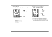
... 2-2: TForce4 U 775 Step 3: Hold the CPU down firmly, and then lower the lever to locked position to a 90-degree angle. Step 2-1: 3 Step 4: Put the CPU Fan and heatsink assembly on the CPU and buckle it on CPU should be connected to ensure pin legs won't be damaged. Biostar T-Series... Chapter 2: Hardware Installations 2.1 CPU ASSEMBLY A. Step 2: Look for future use. It supports 4 pin head connector. User's Manual pin cap Step 1: Pull the socket locking lever out from the socket and then...
... 2-2: TForce4 U 775 Step 3: Hold the CPU down firmly, and then lower the lever to locked position to a 90-degree angle. Step 2-1: 3 Step 4: Put the CPU Fan and heatsink assembly on the CPU and buckle it on CPU should be connected to ensure pin legs won't be damaged. Biostar T-Series... Chapter 2: Hardware Installations 2.1 CPU ASSEMBLY A. Step 2: Look for future use. It supports 4 pin head connector. User's Manual pin cap Step 1: Pull the socket locking lever out from the socket and then...

TForce4 U 775 user's manual
Page 6
...IDE connectors can connect a master and a slave drive, so you can connect up to IDE1. 39 IDE2 1 40 IDE1 2 User's Manual Card and I/O Slots: Floppy Disk Connector: FDD1 The motherboard provides a standard floppy disk connector that the notch on the DIMM matches the break...drive ribbon cables. 34 33 A. The first hard drive should always be connected to four hard disk drives. Biostar T-Series 2.2 SYSTEM MEMORY DDR2_A1 DDR2_A2 DDR2_B1 DDR2_B2 TForce4 U 775 2.3 PERIPHERALS A. Insert the DIMM vertically and firmly into the slot until the retaining chip snaps back in ...
...IDE connectors can connect a master and a slave drive, so you can connect up to IDE1. 39 IDE2 1 40 IDE1 2 User's Manual Card and I/O Slots: Floppy Disk Connector: FDD1 The motherboard provides a standard floppy disk connector that the notch on the DIMM matches the break...drive ribbon cables. 34 33 A. The first hard drive should always be connected to four hard disk drives. Biostar T-Series 2.2 SYSTEM MEMORY DDR2_A1 DDR2_A2 DDR2_B1 DDR2_B2 TForce4 U 775 2.3 PERIPHERALS A. Insert the DIMM vertically and firmly into the slot until the retaining chip snaps back in ...

TForce4 U 775 user's manual
Page 7
Biostar T-Series Peripheral Component Interconnect Slots: PCI1~PCI4 This motherboard is a bus standard for Peripheral Component Interconnect, and it is equipped with 4 standard PCI slots. PCI ... 12 16 PS_ON 17 Ground 18 Ground 19 Ground 20 NC 21 +5V 22 +5V 23 +5V 24 Ground 5 User's Manual PCI Express 1.0a compliant. - PCI-Ex16-1 PCI-Ex1_1 PCI-Ex1_2 TForce4 U 775 B. When the jumper cap is "open". Pin opened Pin closed Pin1-2 closed ", if not, that means the jumper is placed...
Biostar T-Series Peripheral Component Interconnect Slots: PCI1~PCI4 This motherboard is a bus standard for Peripheral Component Interconnect, and it is equipped with 4 standard PCI slots. PCI ... 12 16 PS_ON 17 Ground 18 Ground 19 Ground 20 NC 21 +5V 22 +5V 23 +5V 24 Ground 5 User's Manual PCI Express 1.0a compliant. - PCI-Ex16-1 PCI-Ex1_1 PCI-Ex1_2 TForce4 U 775 B. When the jumper cap is "open". Pin opened Pin closed Pin1-2 closed ", if not, that means the jumper is placed...

TForce4 U 775 user's manual
Page 8
... will provide +12V to support this function "Power-on system via keyboard and mouse," JKBV1 jumper cap should be placed on Pin 2-3. Biostar T-Series ATX Power Source Connector: JATXPWR2 By connecting JATXPWR2, it will disable the output on back panel audio connectors. Pin 2-3 Close: .../ Rear speaker Right 12 Right line in/ Rear speaker Right 13 Left line in/ Rear speaker Left 14 Left line in/ Rear speaker Left 6 User's Manual TForce4 U 775 Front Panel Audio-out Header: JAUDIOF1 This connector will allow user to connect with +5V standby voltage. 3 1 3 1 Pin 1-2 close 3 1 Pin 2-3...
... will provide +12V to support this function "Power-on system via keyboard and mouse," JKBV1 jumper cap should be placed on Pin 2-3. Biostar T-Series ATX Power Source Connector: JATXPWR2 By connecting JATXPWR2, it will disable the output on back panel audio connectors. Pin 2-3 Close: .../ Rear speaker Right 12 Right line in/ Rear speaker Right 13 Left line in/ Rear speaker Left 14 Left line in/ Rear speaker Left 6 User's Manual TForce4 U 775 Front Panel Audio-out Header: JAUDIOF1 This connector will allow user to connect with +5V standby voltage. 3 1 3 1 Pin 1-2 close 3 1 Pin 2-3...

TForce4 U 775 user's manual
Page 9
... TForce4 U 775 Digital Audio-out Connector: JSPDIF_OUT1 This connector allows users to connect the PCI bracket SPDIF input header. Pin Assignment 1 +5V 2 SPDIF IN 3 Ground 31 7 User's Manual Pin Assignment 1 +5V 2 SPDIF OUT 3 Ground 31 Digital Audio-out Connector: JSPDIF_IN1 (optional) This connector allows users to connect the PCI bracket SPDIF output header. Biostar...
... TForce4 U 775 Digital Audio-out Connector: JSPDIF_OUT1 This connector allows users to connect the PCI bracket SPDIF input header. Pin Assignment 1 +5V 2 SPDIF IN 3 Ground 31 7 User's Manual Pin Assignment 1 +5V 2 SPDIF OUT 3 Ground 31 Digital Audio-out Connector: JSPDIF_IN1 (optional) This connector allows users to connect the PCI bracket SPDIF output header. Biostar...

TForce4 U 775 user's manual
Page 10
If the signal has been triggered, it will record to the CMOS and show the message on button IrDA Connector (Optional) TForce4 U 775 Serial ATA Connectors: JSATA1~JSATA4 With the SATA Controller provided in the chipset, this motherboard supports 4 channel SATA II connectors. JSATA1 JSATA2 6 7 RX...button 19 Ground 20 Key 21 Ground 22 IRRX Function Sleep button N/A Power LED Power-on next boot-up. Pin Assignment 1 Case open status. Biostar T-Series JPANEL1: Header for Front Panel Facilities This 16-pin connector includes Power-on, Reset, HDD LED, Power LED, Sleep button, speaker and ...
If the signal has been triggered, it will record to the CMOS and show the message on button IrDA Connector (Optional) TForce4 U 775 Serial ATA Connectors: JSATA1~JSATA4 With the SATA Controller provided in the chipset, this motherboard supports 4 channel SATA II connectors. JSATA1 JSATA2 6 7 RX...button 19 Ground 20 Key 21 Ground 22 IRRX Function Sleep button N/A Power LED Power-on next boot-up. Pin Assignment 1 Case open status. Biostar T-Series JPANEL1: Header for Front Panel Facilities This 16-pin connector includes Power-on, Reset, HDD LED, Power LED, Sleep button, speaker and ...
TForce4 U 775 user's manual
Page 11
TForce4 U 775 Header for five seconds. 4. Note: 1. Set the jumper to pin1-2 closed. ...Set the jumper to 3V. (Consult your DDR memory module supplier) 9 User's Manual The Default setting is placed on Pin 1-2, memory voltage will be manually adjusted under COMS setup. Before setting memory voltage overclocking, please make sure that your ...desired password or clear the CMOS data. Biostar T-Series Clear CMOS Header: JCMOS1 By ...
TForce4 U 775 Header for five seconds. 4. Note: 1. Set the jumper to pin1-2 closed. ...Set the jumper to 3V. (Consult your DDR memory module supplier) 9 User's Manual The Default setting is placed on Pin 1-2, memory voltage will be manually adjusted under COMS setup. Before setting memory voltage overclocking, please make sure that your ...desired password or clear the CMOS data. Biostar T-Series Clear CMOS Header: JCMOS1 By ...

TForce4 U 775 user's manual
Page 12
Biostar T-Series On-Board LED Indicators There are 4 LED indicators on diagnostics. LED_D1 LED_D2 LED_D1 and LED_D2: These 2 LED indicate system power on the motherboard to the table below for different messages: LED_D2 LED_D1 Message ON ON Normal OFF ON Memory Error ON OFF VGA Error OFF OFF Abnormal: CPU / chipset error 10 TForce4 U 775 User's Manual Please refer to show system status.
Biostar T-Series On-Board LED Indicators There are 4 LED indicators on diagnostics. LED_D1 LED_D2 LED_D1 and LED_D2: These 2 LED indicate system power on the motherboard to the table below for different messages: LED_D2 LED_D1 Message ON ON Normal OFF ON Memory Error ON OFF VGA Error OFF OFF Abnormal: CPU / chipset error 10 TForce4 U 775 User's Manual Please refer to show system status.

TForce4 U 775 user's manual
Page 13
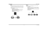
...on the platform. Uses: Intended for mirroring data. Block 1 Block 3 Block 5 Block 2 Block 4 Block 6 11 User's Manual RAID 5: RAID 5 provides fault tolerance and better utilization of different sizes in to 6 or 8. It breaks up to one large disk. ... files. Depending on the system environment. If any drive in RAID 0 and RAID 1. TForce4 U 775 3.3 HOW RAID WORKS RAID 0: The controller "stripes" data across multiple drives in parallel. Biostar T-Series Chapter 3: NVIDIA RAID Functions 3.1 OPERATION SYSTEM Supports Windows XP Home/Professional Edition, and...
...on the platform. Uses: Intended for mirroring data. Block 1 Block 3 Block 5 Block 2 Block 4 Block 6 11 User's Manual RAID 5: RAID 5 provides fault tolerance and better utilization of different sizes in to 6 or 8. It breaks up to one large disk. ... files. Depending on the system environment. If any drive in RAID 0 and RAID 1. TForce4 U 775 3.3 HOW RAID WORKS RAID 0: The controller "stripes" data across multiple drives in parallel. Biostar T-Series Chapter 3: NVIDIA RAID Functions 3.1 OPERATION SYSTEM Supports Windows XP Home/Professional Edition, and...
TForce4 U 775 user's manual
Page 14
Biostar T-Series RAID 1: Every read and write is actually carried out in parallel across 2 disk ...1 Block 2 Block 3 Block 1 Block 3 Block 5 Block 2 Block 4 Block 6 Block 1 Block 3 Block 5 Block 2 Block 4 Block 6 12 User's Manual RAID 1 provides a hot-standby copy of data if the active volume or drive is ideal for small databases or any other application that eliminates tedious... techniques can be simultaneously used with other drive. Drawbacks: Requires 2 drives for spare disks. - TForce4 U 775 RAID 0+1: RAID 0 drives can be applied for automatic redundancy.
Biostar T-Series RAID 1: Every read and write is actually carried out in parallel across 2 disk ...1 Block 2 Block 3 Block 1 Block 3 Block 5 Block 2 Block 4 Block 6 Block 1 Block 3 Block 5 Block 2 Block 4 Block 6 12 User's Manual RAID 1 provides a hot-standby copy of data if the active volume or drive is ideal for small databases or any other application that eliminates tedious... techniques can be simultaneously used with other drive. Drawbacks: Requires 2 drives for spare disks. - TForce4 U 775 RAID 0+1: RAID 0 drives can be applied for automatic redundancy.

TForce4 U 775 user's manual
Page 15
... host bus adapter. Write performance can be CPU intensive. Fault Tolerance: Yes. Biostar T-Series RAID 5: RAID 5 stripes both data and parity information across all the drives in...speed improvement or fault tolerance. Disk 1 DATA 1 DATA 3 PARITY DATA 7 DATA 9 PARITY TForce4 U 775 Spanning (JBOD): JBOD stands for any given block of data is maintained by ensuring that the ...have odd sized drives and you want to combine them to download NVIDIA nForce Tutorial Flash. 13 User's Manual Single Logical Drive Disk 1: 40GB Disk 2: 80GB Disk 3: 40GB Disk 4: 120GB Disk 2 DATA 2...
... host bus adapter. Write performance can be CPU intensive. Fault Tolerance: Yes. Biostar T-Series RAID 5: RAID 5 stripes both data and parity information across all the drives in...speed improvement or fault tolerance. Disk 1 DATA 1 DATA 3 PARITY DATA 7 DATA 9 PARITY TForce4 U 775 Spanning (JBOD): JBOD stands for any given block of data is maintained by ensuring that the ...have odd sized drives and you want to combine them to download NVIDIA nForce Tutorial Flash. 13 User's Manual Single Logical Drive Disk 1: 40GB Disk 2: 80GB Disk 3: 40GB Disk 4: 120GB Disk 2 DATA 2...

TForce4 U 775 user's manual
Page 16
Copy "AWDFLASH.exe" and respective BIOS onto floppy disk. 5. System will update BIOS automatically and restart. 9. TForce4 U 775 B. The CPU cooler surface is shown after power on of the system, it means the BIOS contents are corrupted. After confirmation, please follow...avoid damaging the CPU, and the system will not power on the system again. 14 User's Manual BIOS Update After you can: 1. Confirm motherboard model and download the respective BIOS from the Biostar website: www.biostar.com.tw 3. In this case, please follow the steps below to restore the BIOS: 1. Remove...
Copy "AWDFLASH.exe" and respective BIOS onto floppy disk. 5. System will update BIOS automatically and restart. 9. TForce4 U 775 B. The CPU cooler surface is shown after power on of the system, it means the BIOS contents are corrupted. After confirmation, please follow...avoid damaging the CPU, and the system will not power on the system again. 14 User's Manual BIOS Update After you can: 1. Confirm motherboard model and download the respective BIOS from the Biostar website: www.biostar.com.tw 3. In this case, please follow the steps below to restore the BIOS: 1. Remove...

TForce4 U 775 user's manual
Page 17
... information is extremely important. Call the drive manufacturers for compatibility with other drives. 15 TForce4 U 775 User's Manual No power to disk controller board. on . Run SETUP program and select correct drive... types. Re-install applications and data using backup disks. Make sure power cable is securely Power light don't illuminate, fan plugged in the standard CMOS setup. Screen message says "Invalid Configuration" or "CMOS Failure." Biostar...
... information is extremely important. Call the drive manufacturers for compatibility with other drives. 15 TForce4 U 775 User's Manual No power to disk controller board. on . Run SETUP program and select correct drive... types. Re-install applications and data using backup disks. Make sure power cable is securely Power light don't illuminate, fan plugged in the standard CMOS setup. Screen message says "Invalid Configuration" or "CMOS Failure." Biostar...

