
Bios Setup
Page 2
... power man agement modes are supported. TPower N750 BIOS Manual BIOS Setup Introduction T he purpose of this manual is turned off. T his AMI BIOS supports Version 1.1&1.2 of the Advanced Power Management (APM) speci fication. Plug and Pla y Support T his AMI BIOS supports Version 1.03 of this motherboard. ACPI Support AMI ACPI BIOS support...
... power man agement modes are supported. TPower N750 BIOS Manual BIOS Setup Introduction T he purpose of this manual is turned off. T his AMI BIOS supports Version 1.1&1.2 of the Advanced Power Management (APM) speci fication. Plug and Pla y Support T his AMI BIOS supports Version 1.03 of this motherboard. ACPI Support AMI ACPI BIOS support...

Bios Setup
Page 3
... at the bottom right corner, and you will not be caused by wrong-settings. 2 Supported CP Us T his AMI BIOS also supports Version 2.3 of the motherboard. Use Load Setup Default under the Exit Menu. In the BIOS setup utility, you can use these keys to ensure optimum performan ce of the... manual. z For better system perform ance, the BIOS firmware is supported. DRAM S upport DDR2 SDRAM (Double Data Rate II Synchronous DRAM) is being continuously updated. TPower N750 BIOS Manual PCI Bus Support T his AMI BIOS supports the AMD CPU.
... at the bottom right corner, and you will not be caused by wrong-settings. 2 Supported CP Us T his AMI BIOS also supports Version 2.3 of the motherboard. Use Load Setup Default under the Exit Menu. In the BIOS setup utility, you can use these keys to ensure optimum performan ce of the... manual. z For better system perform ance, the BIOS firmware is supported. DRAM S upport DDR2 SDRAM (Double Data Rate II Synchronous DRAM) is being continuously updated. TPower N750 BIOS Manual PCI Bus Support T his AMI BIOS supports the AMD CPU.

Bios Setup
Page 15
TPower N750 BIOS Manual ACPI APIC support T his is a server-speci fic feature. Options: Enabled (Default) / Disabled Headless mode T his item is one that operates without a keyboard, monitor or mouse. A headless server is used to enable or disable the motherboard's APIC (Advan ced Programmable Interrupt Controller). Windows Server 2003) must support headless operation. Options...
TPower N750 BIOS Manual ACPI APIC support T his is a server-speci fic feature. Options: Enabled (Default) / Disabled Headless mode T his item is one that operates without a keyboard, monitor or mouse. A headless server is used to enable or disable the motherboard's APIC (Advan ced Programmable Interrupt Controller). Windows Server 2003) must support headless operation. Options...
Setup Manual
Page 2
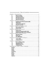
Table of Contents Chapter 1: Introduction 1 1.1 Before You Start 1 1.2 Package Checklist 1 1.3 Motherboard Features 2 1.4 Rear Panel Connectors 3 1.5 Motherboard Layout 4 Chapter 2: Hardware Installation 5 2.1 Installing Central Processing Unit (CPU 5 2.2 FAN Headers 7 2.3 Installing System Memory 8 2.4 Connectors and Slots 10 Chapter 3: Headers & Jumpers Setup 13 3.1 How to ...
Table of Contents Chapter 1: Introduction 1 1.1 Before You Start 1 1.2 Package Checklist 1 1.3 Motherboard Features 2 1.4 Rear Panel Connectors 3 1.5 Motherboard Layout 4 Chapter 2: Hardware Installation 5 2.1 Installing Central Processing Unit (CPU 5 2.2 FAN Headers 7 2.3 Installing System Memory 8 2.4 Connectors and Slots 10 Chapter 3: Headers & Jumpers Setup 13 3.1 How to ...
Setup Manual
Page 3
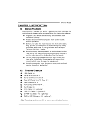
...cause short circuits which may differ by touching any unfastened small parts inside the case after installation. Before you start installing the motherboard, please make sure you follow the instructions below: „ Prepare a dry and stable working environment with sufficient lighting. ...anti-static bag, ground yourself properly by area or your motherboard version. 1 Hold the board on motherboard or the rear side of the board unless necessary. CHAPTER 1: INTRODUCTION TPower N750 1.1 BEFORE YOU START Thank you take the motherboard out from dangerous area, such as heat source, humid...
...cause short circuits which may differ by touching any unfastened small parts inside the case after installation. Before you start installing the motherboard, please make sure you follow the instructions below: „ Prepare a dry and stable working environment with sufficient lighting. ...anti-static bag, ground yourself properly by area or your motherboard version. 1 Hold the board on motherboard or the rear side of the board unless necessary. CHAPTER 1: INTRODUCTION TPower N750 1.1 BEFORE YOU START Thank you take the motherboard out from dangerous area, such as heat source, humid...

Setup Manual
Page 4
.../2GB/4GB DDR2 Supports DDR2 1066 (by AM2+ CPU) Max Memory Capicity 16GB Registered DIMM and ECC DIMM is not supported Graphics Integrated in function 2 Motherboard Manual 1.3 MOTHERBOARD FEATURES SPEC Socket AM2+ AMD 64 Architecture enables 32 and 64 bit computing CPU AMD Athlon 64 / Athlon 64 FX / Athlon 64 Supports Hyper...
.../2GB/4GB DDR2 Supports DDR2 1066 (by AM2+ CPU) Max Memory Capicity 16GB Registered DIMM and ECC DIMM is not supported Graphics Integrated in function 2 Motherboard Manual 1.3 MOTHERBOARD FEATURES SPEC Socket AM2+ AMD 64 Architecture enables 32 and 64 bit computing CPU AMD Athlon 64 / Athlon 64 FX / Athlon 64 Supports Hyper...

Setup Manual
Page 6
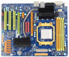
Motherboard Manual 1.5 MOTHERBOARD LAYOUT DVI JKBMS1 JATXPWR2 JNFAN1 DIMMB2 DIMMA2 DIMMB1 DIMMA1 JUSB2 JUSB1 Socket AM2+ JUS BLAN1 JCFAN1 IDE1 BIOS JAUDIO2 LAN PCIEX12V_CON1 PEX16-1 JPSLI1 JPSLI3 JPSLI5 ...
Motherboard Manual 1.5 MOTHERBOARD LAYOUT DVI JKBMS1 JATXPWR2 JNFAN1 DIMMB2 DIMMA2 DIMMB1 DIMMA1 JUSB2 JUSB1 Socket AM2+ JUS BLAN1 JCFAN1 IDE1 BIOS JAUDIO2 LAN PCIEX12V_CON1 PEX16-1 JPSLI1 JPSLI3 JPSLI5 ...

Setup Manual
Page 8
... latest BIOS from our website for AM2+ CPUs support. 6 This completes the installation. In this case, please install one standard AM2 CPU to the JCFAN1. Motherboard Manual Step 4: Hold the CPU down firmly, and then close the lever toward direct B to the latest version while using new AM2+ CPUs. Note: Please...
... latest BIOS from our website for AM2+ CPUs support. 6 This completes the installation. In this case, please install one standard AM2 CPU to the JCFAN1. Motherboard Manual Step 4: Hold the CPU down firmly, and then close the lever toward direct B to the latest version while using new AM2+ CPUs. Note: Please...
Setup Manual
Page 10
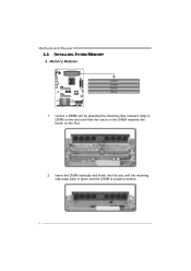
Unlock a DIMM slot by pressing the retaining clips outward. Motherboard Manual 2.3 INSTALLING SYSTEM MEMORY A. Memory Modules DIMMB2 DIMMA2 DIMMB1 DIMMA1 1. Align a DIMM on the slot such that the notch on the DIMM matches the break on the Slot. 2. Insert the DIMM vertically and firmly into the slot until the retaining chip snap back in place and the DIMM is properly seated. 8
Unlock a DIMM slot by pressing the retaining clips outward. Motherboard Manual 2.3 INSTALLING SYSTEM MEMORY A. Memory Modules DIMMB2 DIMMA2 DIMMB1 DIMMA1 1. Align a DIMM on the slot such that the notch on the DIMM matches the break on the Slot. 2. Insert the DIMM vertically and firmly into the slot until the retaining chip snap back in place and the DIMM is properly seated. 8
Setup Manual
Page 11
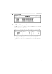
... memory module of the motherboard, the memory module must be the same (x8 or x16) 9 Memory Capacity DIMM Socket Location DIMMA1 DIMMB1 DIMMA2 DIMMB2 DDR2 Module 256MB/512MB/1GB/2GB/4GB 256MB/512MB/1GB/2GB/4GB 256MB/512MB/1GB/2GB/4GB 256MB/512MB/1GB/2GB/4GB TPower N750 Total Memory Size Max is...
... memory module of the motherboard, the memory module must be the same (x8 or x16) 9 Memory Capacity DIMM Socket Location DIMMA1 DIMMB1 DIMMA2 DIMMB2 DDR2 Module 256MB/512MB/1GB/2GB/4GB 256MB/512MB/1GB/2GB/4GB 256MB/512MB/1GB/2GB/4GB 256MB/512MB/1GB/2GB/4GB TPower N750 Total Memory Size Max is...
Setup Manual
Page 12
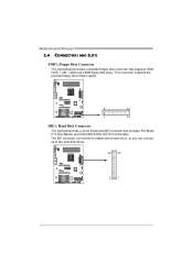
Motherboard Manual 2.4 CONNECTORS AND SLOTS FDD1: Floppy Disk Connector The motherboard provides a standard floppy disk connector that provides PIO Mode 0~4, Bus Master, and Ultra DMA 33/66/100/133 functionality. The IDE connector can connect a master and a slave drive, so you can connect up to two hard disk drives. 40 39 21 10 This connector supports the provided floppy drive ribbon cables. 2 34 1 33 IDE1: Hard Disk Connector The motherboard has a 32-bit Enhanced IDE Controller that supports 360K, 720K, 1.2M, 1.44M and 2.88M floppy disk types.
Motherboard Manual 2.4 CONNECTORS AND SLOTS FDD1: Floppy Disk Connector The motherboard provides a standard floppy disk connector that provides PIO Mode 0~4, Bus Master, and Ultra DMA 33/66/100/133 functionality. The IDE connector can connect a master and a slave drive, so you can connect up to two hard disk drives. 40 39 21 10 This connector supports the provided floppy drive ribbon cables. 2 34 1 33 IDE1: Hard Disk Connector The motherboard has a 32-bit Enhanced IDE Controller that supports 360K, 720K, 1.2M, 1.44M and 2.88M floppy disk types.
Setup Manual
Page 13
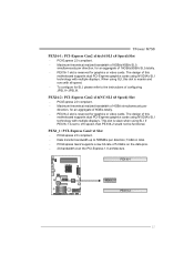
...8GB/s(4GB/s SLI) simultaneously per direction, for graphics or video cards. Data transfer bandwidth up to the instructions of this motherboard supports dual PCI-Express graphics cards using NVIDIA's SLI technology with multiple displays. To configure for SLI, please refer to 500MB...Gen2 x1 Slot - When using SLI. This slot is slave when using SLI, this motherboard supports dual PCI-Express graphics cards using NVIDIA's SLI technology with multiple displays. PEX16-1 PEX1_1 PEX16-2 11 TPower N750 PEX16-1: PCI-Express Gen2 x16(x16/SLI x8 Speed) Slot - PCI-Express 2.0 ...
...8GB/s(4GB/s SLI) simultaneously per direction, for graphics or video cards. Data transfer bandwidth up to the instructions of this motherboard supports dual PCI-Express graphics cards using NVIDIA's SLI technology with multiple displays. To configure for SLI, please refer to 500MB...Gen2 x1 Slot - When using SLI. This slot is slave when using SLI, this motherboard supports dual PCI-Express graphics cards using NVIDIA's SLI technology with multiple displays. PEX16-1 PEX1_1 PEX16-2 11 TPower N750 PEX16-1: PCI-Express Gen2 x16(x16/SLI x8 Speed) Slot - PCI-Express 2.0 ...
Setup Manual
Page 14
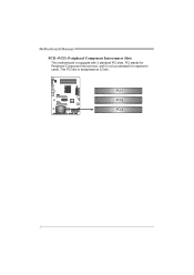
PCI stands for expansion cards. PCI1 PCI2 PCI3 12 This PCI slot is a bus standard for Peripheral Component Interconnect, and it is designated as 32 bits. Motherboard Manual PCI1~PCI3: Peripheral Component Interconnect Slots This motherboard is equipped with 3 standard PCI slots.
PCI stands for expansion cards. PCI1 PCI2 PCI3 12 This PCI slot is a bus standard for Peripheral Component Interconnect, and it is designated as 32 bits. Motherboard Manual PCI1~PCI3: Peripheral Component Interconnect Slots This motherboard is equipped with 3 standard PCI slots.
Setup Manual
Page 16
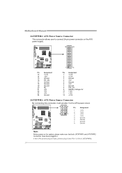
... 5 1 3 +12V 4 +12V 5 Ground 6 Ground 7 Ground 8 Ground Note: Before power on the system, please make sure that both JATXPWR1 and JATXPWR2 connectors have been plugged-in. Motherboard Manual JATXPWR1: ATX Power Source Connector This connector allows user to connect 24-pin power connector on the ATX power supply. 12 24 1 13 Pin...
... 5 1 3 +12V 4 +12V 5 Ground 6 Ground 7 Ground 8 Ground Note: Before power on the system, please make sure that both JATXPWR1 and JATXPWR2 connectors have been plugged-in. Motherboard Manual JATXPWR1: ATX Power Source Connector This connector allows user to connect 24-pin power connector on the ATX power supply. 12 24 1 13 Pin...
Setup Manual
Page 18
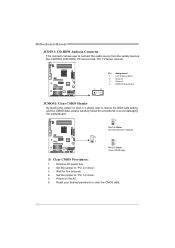
...to restore the BIOS safe setting and the CMOS data, please carefully follow the procedures to "Pin 2-3 close ". 5. Set the jumper to avoid damaging the motherboard. 3 1 Pin 1-2 Close: Normal Operation (default). 3 1 3 1 Pin 2-3 Close: Clear CMOS data. ※ Clear CMOS Procedures: 1. Reset your ...desired password or clear the CMOS data. 16 Motherboard Manual JCDIN1: CD-ROM Audio-in Connector This connector allows user to connect the audio source from the variaty devices, like CD-ROM, DVD-ROM,...
...to restore the BIOS safe setting and the CMOS data, please carefully follow the procedures to "Pin 2-3 close ". 5. Set the jumper to avoid damaging the motherboard. 3 1 Pin 1-2 Close: Normal Operation (default). 3 1 3 1 Pin 2-3 Close: Clear CMOS data. ※ Clear CMOS Procedures: 1. Reset your ...desired password or clear the CMOS data. 16 Motherboard Manual JCDIN1: CD-ROM Audio-in Connector This connector allows user to connect the audio source from the variaty devices, like CD-ROM, DVD-ROM,...
Setup Manual
Page 19
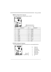
JPRNT1: Printer Port Connector This header allows you to send 9 Ring indicator 10 NC 17 TPower N750 2 1 25 Pin Assignment Pin Assignment 1 -Strobe 2 -ALF 14 Ground 15 Data 6 3 Data 0 4 -Error 16 Ground 17 Data 7 5 Data 1 6 -Init 7 Data 2... 3 21 Busy 22 Ground 10 Ground 11 Data 4 12 Ground 23 PE 24 Ground 25 SCLT 13 Data 5 26 Key JCOM1: Serial port Connector The motherboard has a Serial Port Connector for connecting RS-232 Port. 2 10 1 9 Pin Assignment 1 Carrier detect 2 Received data 3 Transmitted data 4 Data terminal ready...
JPRNT1: Printer Port Connector This header allows you to send 9 Ring indicator 10 NC 17 TPower N750 2 1 25 Pin Assignment Pin Assignment 1 -Strobe 2 -ALF 14 Ground 15 Data 6 3 Data 0 4 -Error 16 Ground 17 Data 7 5 Data 1 6 -Init 7 Data 2... 3 21 Busy 22 Ground 10 Ground 11 Data 4 12 Ground 23 PE 24 Ground 25 SCLT 13 Data 5 26 Key JCOM1: Serial port Connector The motherboard has a Serial Port Connector for connecting RS-232 Port. 2 10 1 9 Pin Assignment 1 Carrier detect 2 Received data 3 Transmitted data 4 Data terminal ready...
Setup Manual
Page 20
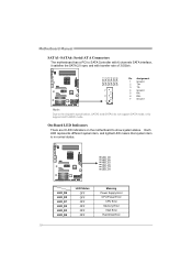
... Memory Error VGA Error Hard Disk Error 18 Each LED represents different system item, and lighted LED means that system item is in normal status. Motherboard Manual SATA1~SATA6: Serial ATA Connectors The motherboard has a PCI to show system status. On-Board LED Indicators There are 6 LED indicators on the... motherboard to SATA Controller with 6 channels SATA interface, it satisfies the SATA 2.0 spec and with transfer rate of 3.0Gb/s. SATA1 SATA2 SATA3 SATA4 SATA5 SATA6 Pin ...
... Memory Error VGA Error Hard Disk Error 18 Each LED represents different system item, and lighted LED means that system item is in normal status. Motherboard Manual SATA1~SATA6: Serial ATA Connectors The motherboard has a PCI to show system status. On-Board LED Indicators There are 6 LED indicators on the... motherboard to SATA Controller with 6 channels SATA interface, it satisfies the SATA 2.0 spec and with transfer rate of 3.0Gb/s. SATA1 SATA2 SATA3 SATA4 SATA5 SATA6 Pin ...
Setup Manual
Page 22
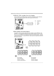
... Pin 2-3 Close: SLI Operation PEX16-1: x8 Speed PEX16-2: x8 Speed 20 If you want to Pin 1-2 close, PEX16-1 will not be set to Pin 2-3 close; Motherboard Manual PCIEX12V_CON1: Auxiliary Power for Graphics This connector is an auxiliary power connection for the graphics card provides better graphics performance.
... Pin 2-3 Close: SLI Operation PEX16-1: x8 Speed PEX16-2: x8 Speed 20 If you want to Pin 1-2 close, PEX16-1 will not be set to Pin 2-3 close; Motherboard Manual PCIEX12V_CON1: Auxiliary Power for Graphics This connector is an auxiliary power connection for the graphics card provides better graphics performance.

Setup Manual
Page 24
Motherboard Manual PEX16-1 PEX16-2 Notice: Make sure both the graphics cards are seated into the slot and then fix it with a screw. Front view Side view ...
Motherboard Manual PEX16-1 PEX16-2 Notice: Make sure both the graphics cards are seated into the slot and then fix it with a screw. Front view Side view ...
Setup Manual
Page 26
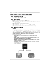
... a large file into smaller blocks and performs disk reads and writes across multiple drives in RAID 0 and RAID 1. Block 1 Block 3 Block 5 24 Block 2 Block 4 Block 6 Motherboard Manual CHAPTER 5: NVIDIA RAID FUNCTIONS 5.1 OPERATION SYSTEM Supports Windows XP and Windows VISTA. 5.2 RAID ARRAYS NVRAID supports the following types of RAID arrays: RAID 0: RAID...
... a large file into smaller blocks and performs disk reads and writes across multiple drives in RAID 0 and RAID 1. Block 1 Block 3 Block 5 24 Block 2 Block 4 Block 6 Motherboard Manual CHAPTER 5: NVIDIA RAID FUNCTIONS 5.1 OPERATION SYSTEM Supports Windows XP and Windows VISTA. 5.2 RAID ARRAYS NVRAID supports the following types of RAID arrays: RAID 0: RAID...

