Setup Manual
Page 2
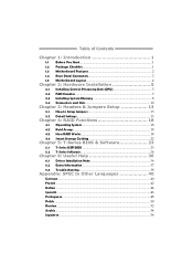
Table of Contents Chapter 1: Introduction 1 1.1 Before You Start 1 1.2 Package Checklist 1 1.3 Motherboard Features 2 1.4 Rear Panel Connectors 3 1.5 Motherboard Layout 4 Chapter 2: Hardware Installation 5 2.1 Installing Central Processing Unit (CPU 5 2.2 FAN Headers 7 2.3 Installing System Memory 8 2.4 Connectors and Slots 10 Chapter 3: Headers & Jumpers Setup 13 3.1 How to ...
Table of Contents Chapter 1: Introduction 1 1.1 Before You Start 1 1.2 Package Checklist 1 1.3 Motherboard Features 2 1.4 Rear Panel Connectors 3 1.5 Motherboard Layout 4 Chapter 2: Hardware Installation 5 2.1 Installing Central Processing Unit (CPU 5 2.2 FAN Headers 7 2.3 Installing System Memory 8 2.4 Connectors and Slots 10 Chapter 3: Headers & Jumpers Setup 13 3.1 How to ...
Setup Manual
Page 3
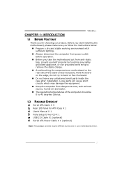
... Driver CD X 1 USB 2.0 Cable X1 (optional) Serial ATA Power Cable X 1 (optional) Note: The package contents may be different due to area or your motherboard version. 1 Hold the board on the edge, do not try to remove the static charge. „ Avoid touching the components on...bend or flex the board. „ Do not leave any unfastened small parts inside the case after installation. CHAPTER 1: INTRODUCTION TZ68A+ 1.1 BEFORE YOU START Thank you take the motherboard out from dangerous area, such as heat source, humid air and water. „ The operating temperatures of the board unless ...
... Driver CD X 1 USB 2.0 Cable X1 (optional) Serial ATA Power Cable X 1 (optional) Note: The package contents may be different due to area or your motherboard version. 1 Hold the board on the edge, do not try to remove the static charge. „ Avoid touching the components on...bend or flex the board. „ Do not leave any unfastened small parts inside the case after installation. CHAPTER 1: INTRODUCTION TZ68A+ 1.1 BEFORE YOU START Thank you take the motherboard out from dangerous area, such as heat source, humid air and water. „ The operating temperatures of the board unless ...
Setup Manual
Page 4
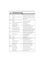
Motherboard Manual 1.3 MOTHERBOARD FEATURES SPEC CPU Chipset Socket 1155 Intel Core i7 / i5 / i3 / Pentium / Celeron processor Intel Z68 Supports Execute Disable Bit / Enhanced Intel SpeedStep® / Intel ...
Motherboard Manual 1.3 MOTHERBOARD FEATURES SPEC CPU Chipset Socket 1155 Intel Core i7 / i5 / i3 / Pentium / Celeron processor Intel Z68 Supports Execute Disable Bit / Enhanced Intel SpeedStep® / Intel ...
Setup Manual
Page 6
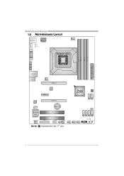
F_USB3 F_USB2 F_USB1 PANEL1 SW_PWR1 4 Motherboard Manual 1.5 MOTHERBOARD LAYOUT HDMI1 U SB_KBMS1 PHS PH3 PH2 PH1 VTT _LED1 ATXPW R2 C PU_FAN1 DVI1 Socket 1155 CPU1 DDR3 _A1 DDR3 _A2 DDR3 _B1 DDR3 _B2 VGA1 RJ45USB 1 AUDIO1 SY S_FA N2 PEX16_1 ATXP WR1 LAN PEX1_1 Z68 BIOS CODEC PEX16_2 SATA2 SATA1 F_AU DIO1 BAT1 J CMOS1 Super I/O JSP DI FOUT1 J_PRINT1 PCI1 PCI2 J_C OM1 SY S_FA N1 SATA6 SATA5 SATA4 SATA3 LED_D2 LED_D1 SW_R ST1 CIR1 Note: ■ represents the 1st pin.
F_USB3 F_USB2 F_USB1 PANEL1 SW_PWR1 4 Motherboard Manual 1.5 MOTHERBOARD LAYOUT HDMI1 U SB_KBMS1 PHS PH3 PH2 PH1 VTT _LED1 ATXPW R2 C PU_FAN1 DVI1 Socket 1155 CPU1 DDR3 _A1 DDR3 _A2 DDR3 _B1 DDR3 _B2 VGA1 RJ45USB 1 AUDIO1 SY S_FA N2 PEX16_1 ATXP WR1 LAN PEX1_1 Z68 BIOS CODEC PEX16_2 SATA2 SATA1 F_AU DIO1 BAT1 J CMOS1 Super I/O JSP DI FOUT1 J_PRINT1 PCI1 PCI2 J_C OM1 SY S_FA N1 SATA6 SATA5 SATA4 SATA3 LED_D2 LED_D1 SW_R ST1 CIR1 Note: ■ represents the 1st pin.
Setup Manual
Page 8
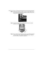
Step 5: Put the CPU Fan and heatsink assembly on the CPU and buckle it on CPU should point forwards this triangular cut edge on socket, and the golden dot on the retention frame. The CPU will fit only in the correct orientation. Connect the CPU FAN power cable into the CPU_FAN1 to complete the installation. Step 4: Hold the CPU down firmly, and then lower the lever to locked position to complete the installation. 6 Motherboard Manual Step 3: Look for the triangular cut edge.
Step 5: Put the CPU Fan and heatsink assembly on the CPU and buckle it on CPU should point forwards this triangular cut edge on socket, and the golden dot on the retention frame. The CPU will fit only in the correct orientation. Connect the CPU FAN power cable into the CPU_FAN1 to complete the installation. Step 4: Hold the CPU down firmly, and then lower the lever to locked position to complete the installation. 6 Motherboard Manual Step 3: Look for the triangular cut edge.
Setup Manual
Page 10
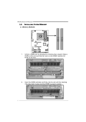
Insert the DIMM vertically and firmly into the slot until the retaining chip snap back in place and the DIMM is properly seated. 8 Align a DIMM on the slot such that the notch on the DIMM matches the break on the Slot. 2. Memory Modules 1. Unlock a DIMM slot by pressing the retaining clips outward. DDR3_A1 DDR3_A2 DDR3_B1 DDR3_B2 Motherboard Manual 2.3 INSTALLING SYSTEM MEMORY A.
Insert the DIMM vertically and firmly into the slot until the retaining chip snap back in place and the DIMM is properly seated. 8 Align a DIMM on the slot such that the notch on the DIMM matches the break on the Slot. 2. Memory Modules 1. Unlock a DIMM slot by pressing the retaining clips outward. DDR3_A1 DDR3_A2 DDR3_B1 DDR3_B2 Motherboard Manual 2.3 INSTALLING SYSTEM MEMORY A.

Setup Manual
Page 12
SATA2 SATA1 7 4 1 Pin Assignment 1 Ground 2 TX+ 3 TX4 Ground 5 RX6 RX+ 7 Ground SATA3~SATA6: Serial ATA2 Connectors The motherboard has a PCI to SATA Controller with 2 channels SATA3 interface, it satisfies the SATA 2.0 spec and with transfer rate of 3.0Gb/s. Motherboard Manual 2.4 CONNECTORS AND SLOTS SATA1/SATA2: Serial ATA3 Connectors The motherboard has a PCI to SATA Controller with 4 channels SATA2 interface, it satisfies the SATA 3.0 spec and with transfer rate of 6.0Gb/s. SATA5 SATA3 SATA6 SATA4 7 4 1 Pin Assignment 1 Ground 2 TX+ 3 TX4 Ground 5 RX6 RX+ 7 Ground 10
SATA2 SATA1 7 4 1 Pin Assignment 1 Ground 2 TX+ 3 TX4 Ground 5 RX6 RX+ 7 Ground SATA3~SATA6: Serial ATA2 Connectors The motherboard has a PCI to SATA Controller with 2 channels SATA3 interface, it satisfies the SATA 2.0 spec and with transfer rate of 3.0Gb/s. Motherboard Manual 2.4 CONNECTORS AND SLOTS SATA1/SATA2: Serial ATA3 Connectors The motherboard has a PCI to SATA Controller with 4 channels SATA2 interface, it satisfies the SATA 3.0 spec and with transfer rate of 6.0Gb/s. SATA5 SATA3 SATA6 SATA4 7 4 1 Pin Assignment 1 Ground 2 TX+ 3 TX4 Ground 5 RX6 RX+ 7 Ground 10
Setup Manual
Page 14
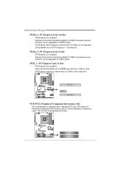
Motherboard Manual PEX16_1: PCI-Express Gen2 x16 Slot - Maximum theoretical realized bandwidth of 8GB/s simultaneously per direction, for an aggregate of 2.5Gb/s on the data pins. - .... - PCI-Express 2.0 compliant. - PEX1_1: PCI-Express Gen2 x1 Slot - PEX16_2: PCI-Express Gen2 x4 Slot - PEX16_ 1 PEX1_ 1 PEX16_ 2 PCI1/PCI2: Peripheral Component Interconnect Slot This motherboard is designated as 32 bits. Data transfer bandwidth up to 500MB/s per direction, for expansion cards. This PCI slot is equipped with 2 standard PCI slots...
Motherboard Manual PEX16_1: PCI-Express Gen2 x16 Slot - Maximum theoretical realized bandwidth of 8GB/s simultaneously per direction, for an aggregate of 2.5Gb/s on the data pins. - .... - PCI-Express 2.0 compliant. - PEX1_1: PCI-Express Gen2 x1 Slot - PEX16_2: PCI-Express Gen2 x4 Slot - PEX16_ 1 PEX1_ 1 PEX16_ 2 PCI1/PCI2: Peripheral Component Interconnect Slot This motherboard is designated as 32 bits. Data transfer bandwidth up to 500MB/s per direction, for expansion cards. This PCI slot is equipped with 2 standard PCI slots...
Setup Manual
Page 16
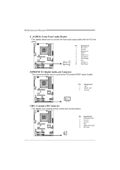
Motherboard Manual F_AUDIO1: Front Panel Audio Header This header allows user to connect the PCI bracket SPDIF output header. Pin Assignment 1 Mic Left in 2 Ground 3 Mic ...
Motherboard Manual F_AUDIO1: Front Panel Audio Header This header allows user to connect the PCI bracket SPDIF output header. Pin Assignment 1 Mic Left in 2 Ground 3 Mic ...
Setup Manual
Page 17
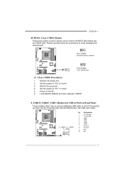
Set the jumper to "Pin 1-2 close ". 3. Set the jumper to "Pin 2-3 close ". 5. TZ68A+ JCMOS1: Clear CMOS Header Placing the jumper on pin2-3 allows user to avoid damaging the motherboard. 13 Pin 1-2 Close: Normal Operation (default). 13 13 Pin 2-3 Close: Clear CMOS data. ※ Clear CMOS Procedures: 1. Remove AC power line. 2. F_USB3 F_ USB1...
Set the jumper to "Pin 1-2 close ". 3. Set the jumper to "Pin 2-3 close ". 5. TZ68A+ JCMOS1: Clear CMOS Header Placing the jumper on pin2-3 allows user to avoid damaging the motherboard. 13 Pin 1-2 Close: Normal Operation (default). 13 13 Pin 2-3 Close: Clear CMOS data. ※ Clear CMOS Procedures: 1. Remove AC power line. 2. F_USB3 F_ USB1...
Setup Manual
Page 18
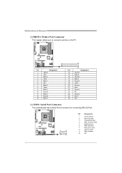
Motherboard Manual J_PRINT1: Printer Port Connector This header allows you to connector printer on the PC. 2 1 Pin Assignment 1 -Strobe 2 -ALF 3 Data 0 4 -Error 5 Data 1 6 -Init 7 Data 2 8 -Scltin 9 ... 17 Data 7 18 Ground 19 -ACK 20 Ground 21 Busy 22 Ground 23 PE 24 Ground 25 SCLT 26 Key J_COM1: Serial Port Connector The motherboard has a Serial Port Connector for connecting RS-232 Port. 2 10 1 9 Pin Assignment 1 Carrier detect 2 Received data 3 Transmitted data 4 Data terminal ready 5 Signal ground 6 Data set...
Motherboard Manual J_PRINT1: Printer Port Connector This header allows you to connector printer on the PC. 2 1 Pin Assignment 1 -Strobe 2 -ALF 3 Data 0 4 -Error 5 Data 1 6 -Init 7 Data 2 8 -Scltin 9 ... 17 Data 7 18 Ground 19 -ACK 20 Ground 21 Busy 22 Ground 23 PE 24 Ground 25 SCLT 26 Key J_COM1: Serial Port Connector The motherboard has a Serial Port Connector for connecting RS-232 Port. 2 10 1 9 Pin Assignment 1 Carrier detect 2 Received data 3 Transmitted data 4 Data terminal ready 5 Signal ground 6 Data set...
Setup Manual
Page 19
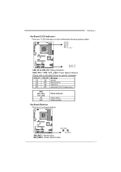
...: CPU / Chipset error. PHS PH1~PH3 VTT_LED ON OFF Phase Indicator Phase Active Phase Inactive On-Board Buttons There are 7 LED indicators on -board buttons. TZ68A+ On-Board LED Indicators There are 2 on the motherboard showing system status. SW_RST1 17
...: CPU / Chipset error. PHS PH1~PH3 VTT_LED ON OFF Phase Indicator Phase Active Phase Inactive On-Board Buttons There are 7 LED indicators on -board buttons. TZ68A+ On-Board LED Indicators There are 2 on the motherboard showing system status. SW_RST1 17
Setup Manual
Page 20
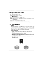
... the array fails, all data is up a large file into smaller blocks and performs disk reads and writes across multiple drives in a RAID 0 array system. Motherboard Manual CHAPTER 4: RAID FUNCTIONS 4.1 OPERATING SYSTEM Supports Windows Vista and Windows 7. 4.2 RAID ARRAYS RAID supports the following types of RAID arrays: RAID 0: RAID 0 defines a disk...
... the array fails, all data is up a large file into smaller blocks and performs disk reads and writes across multiple drives in a RAID 0 array system. Motherboard Manual CHAPTER 4: RAID FUNCTIONS 4.1 OPERATING SYSTEM Supports Windows Vista and Windows 7. 4.2 RAID ARRAYS RAID supports the following types of RAID arrays: RAID 0: RAID 0 defines a disk...
Setup Manual
Page 22
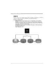
Motherboard Manual RAID 10: RAID 1 drives can be simultaneously used with other RAID levels in a RAID 10 solution for automatic redundancy. Resulting in an array, and ...
Motherboard Manual RAID 10: RAID 1 drives can be simultaneously used with other RAID levels in a RAID 10 solution for automatic redundancy. Resulting in an array, and ...

Setup Manual
Page 24
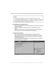
..., and make sure the status of RAID with an Intel SSD drive can be improved better. After all drivers (including Intel(R) Rapid Storage Technology Driver). Motherboard Manual 4.4 SMART STORAGE CACHING With Intel(R) Rapid Storage Technology, the performance of accelerated device has been enabled accelerated. 22 Installing Smart Sotrage Caching 1.
..., and make sure the status of RAID with an Intel SSD drive can be improved better. After all drivers (including Intel(R) Rapid Storage Technology Driver). Motherboard Manual 4.4 SMART STORAGE CACHING With Intel(R) Rapid Storage Technology, the performance of accelerated device has been enabled accelerated. 22 Installing Smart Sotrage Caching 1.
Setup Manual
Page 26
... is always on whenever the system starts up due to control CPU/System Temperature vs. This is an optional process, but not a "must-do" process; Motherboard Manual NOTE Overclock is a brilliant feature to inappropriate overclock actions.
... is always on whenever the system starts up due to control CPU/System Temperature vs. This is an optional process, but not a "must-do" process; Motherboard Manual NOTE Overclock is a brilliant feature to inappropriate overclock actions.
Setup Manual
Page 28
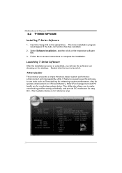
... pre-set OC modes are for special enhancement on the desktop. The driver installation program would appear if the Auto-run function has been enabled. 2. Motherboard Manual 5.2 T-SERIES SOFTWARE Installing T-Series Software 1. Smart-Fan management and PC health are for reference only) 26 Insert the Setup CD to launch it...
... pre-set OC modes are for special enhancement on the desktop. The driver installation program would appear if the Auto-run function has been enabled. 2. Motherboard Manual 5.2 T-SERIES SOFTWARE Installing T-Series Software 1. Smart-Fan management and PC health are for reference only) 26 Insert the Setup CD to launch it...
Setup Manual
Page 29
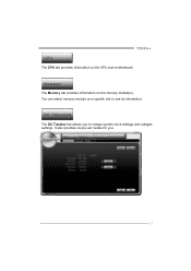
The Memory tab provides information on the CPU and motherboard. The OC Tweaker tab allows you : 27 It also provides six pre-set modes for you to see its information. You can select memory module on a specific slot to change system clock settings and voltages settings. TZ68A+ The CPU tab provides information on the memory module(s).
The Memory tab provides information on the CPU and motherboard. The OC Tweaker tab allows you : 27 It also provides six pre-set modes for you to see its information. You can select memory module on a specific slot to change system clock settings and voltages settings. TZ68A+ The CPU tab provides information on the memory module(s).
Setup Manual
Page 30
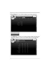
Motherboard Manual 3 Pre-set related values for different overclocking experience. The HW Monitor tab allows you also can set Modes: V6, V12, AUTO for CPU Smart Fan. 28 Besides, you to monitor hardware voltage, fan speed, and temperature.
Motherboard Manual 3 Pre-set related values for different overclocking experience. The HW Monitor tab allows you also can set Modes: V6, V12, AUTO for CPU Smart Fan. 28 Besides, you to monitor hardware voltage, fan speed, and temperature.
Setup Manual
Page 32
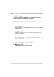
... power consumption are chosen, the system still can keep excellent performance. „ Auto Phase Mode System switches the mode automatically according to save power consumption. Motherboard Manual G.P.U Mode Setting This utility provides five modes, upon your requirements, to improve system performance or to current system loading condition. „ Performance Mode This...
... power consumption are chosen, the system still can keep excellent performance. „ Auto Phase Mode System switches the mode automatically according to save power consumption. Motherboard Manual G.P.U Mode Setting This utility provides five modes, upon your requirements, to improve system performance or to current system loading condition. „ Performance Mode This...


