Setup Manual
Page 1
... the vendor's approval in a residential installation. These limits are trademarks of their respective companies. All the brand and product names are designed to radio communications. Viotech 3200+ Setup Manual FCC Information and Copyright This equipment has been tested and found in this user's manual is not allowed without obligation to Part 15...
... the vendor's approval in a residential installation. These limits are trademarks of their respective companies. All the brand and product names are designed to radio communications. Viotech 3200+ Setup Manual FCC Information and Copyright This equipment has been tested and found in this user's manual is not allowed without obligation to Part 15...

Setup Manual
Page 2
Table of Contents Chapter 1: Introduction 1 1.1 Before You Start 1 1.2 Package Checklist 1 1.3 Motherboard Features 2 1.4 Rear Panel Connectors 3 1.5 Motherboard Layout 4 Chapter 2: Hardware Installation 5 2.1 Installing Central Processing Unit (CPU 5 2.2 FAN Headers 5 2.3 Installing System Memory 6 2.4 Connectors and Slots 8 Chapter 3: Headers & Jumpers Setup 11 3.1 How to Setup Jumpers 11 3.2 Detail Settings 11 Chapter 4: Useful Help 15 4.1 Driver Installation Note 15 5.2 Extra Information 16 5.3 Troubleshooting 17 Appendix: SPEC In Other ...
Table of Contents Chapter 1: Introduction 1 1.1 Before You Start 1 1.2 Package Checklist 1 1.3 Motherboard Features 2 1.4 Rear Panel Connectors 3 1.5 Motherboard Layout 4 Chapter 2: Hardware Installation 5 2.1 Installing Central Processing Unit (CPU 5 2.2 FAN Headers 5 2.3 Installing System Memory 6 2.4 Connectors and Slots 8 Chapter 3: Headers & Jumpers Setup 11 3.1 How to Setup Jumpers 11 3.2 Detail Settings 11 Chapter 4: Useful Help 15 4.1 Driver Installation Note 15 5.2 Extra Information 16 5.3 Troubleshooting 17 Appendix: SPEC In Other ...

Setup Manual
Page 3
... try to 45 degrees Celsius. 1.2 PACKAGE CHECKLIST Rear I/O Panel Shield X 1 Fully Setup Driver CD X 1 (full version manual files inside the case after installation. CHAPTER 1: INTRODUCTION Viotech 3200+ 1.1 BEFORE YOU START Thank you take the motherboard out from anti-static bag, ground yourself properly by touching any unfastened small parts inside ) Serial ATA...
... try to 45 degrees Celsius. 1.2 PACKAGE CHECKLIST Rear I/O Panel Shield X 1 Fully Setup Driver CD X 1 (full version manual files inside the case after installation. CHAPTER 1: INTRODUCTION Viotech 3200+ 1.1 BEFORE YOU START Thank you take the motherboard out from anti-static bag, ground yourself properly by touching any unfastened small parts inside ) Serial ATA...
Setup Manual
Page 4
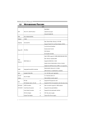
Motherboard Manual 1.3 MOTHERBOARD FEATURES SPEC NanoBGA2 CPU VIA C7-D 1.8G Processor VIA CPU On-board Execute Disable Bit FSB VIA V4 BUS 800MHz Chipset VX900 Graphics Chrome9 HD Max Shared Video Memory is 512MB Support DirectX 9.0 and Pixel Shader (SM2.0) Low Pin Count Interface Super I/O ITE 8728 Environment Control H/W Monitor Fan Speed Controller Each DIMM supports 512MB/1GB/2GB/4GB DDR3 Main Memory DDR3 Slots x 2 Max Memory Capacity 8GB Supports DDR3 800 / 1066 Single Channel Mode DDR3 memory module Registered DIMM and ECC DIMM is not supported SATA Integrated Serial ...
Motherboard Manual 1.3 MOTHERBOARD FEATURES SPEC NanoBGA2 CPU VIA C7-D 1.8G Processor VIA CPU On-board Execute Disable Bit FSB VIA V4 BUS 800MHz Chipset VX900 Graphics Chrome9 HD Max Shared Video Memory is 512MB Support DirectX 9.0 and Pixel Shader (SM2.0) Low Pin Count Interface Super I/O ITE 8728 Environment Control H/W Monitor Fan Speed Controller Each DIMM supports 512MB/1GB/2GB/4GB DDR3 Main Memory DDR3 Slots x 2 Max Memory Capacity 8GB Supports DDR3 800 / 1066 Single Channel Mode DDR3 memory module Registered DIMM and ECC DIMM is not supported SATA Integrated Serial ...

Setup Manual
Page 5
... PS/2 Mouse Real Panel VGA Port I/O LAN Port USB Port Audio Jack Board Size 170 (W) x 220 (L) mm OS Support Windows XP / Vista / 7 Viotech 3200+ SPEC x1 Restore CMOS data to factory default x2 Each connector supports 2 front panel USB ports x1 Each connector supports 1 Printer port x1 Connects to...Mouse x1 Connects to monitor x1 Connects to RJ-45 ethernet cable x4 Connects to USB devices x3 Provide Audio-In/Out and microphone connection Biostar reserves the right to the audio port, please use the Mic In (Pink) audio jack. 3 The input / output function of each ...
... PS/2 Mouse Real Panel VGA Port I/O LAN Port USB Port Audio Jack Board Size 170 (W) x 220 (L) mm OS Support Windows XP / Vista / 7 Viotech 3200+ SPEC x1 Restore CMOS data to factory default x2 Each connector supports 2 front panel USB ports x1 Each connector supports 1 Printer port x1 Connects to...Mouse x1 Connects to monitor x1 Connects to RJ-45 ethernet cable x4 Connects to USB devices x3 Provide Audio-In/Out and microphone connection Biostar reserves the right to the audio port, please use the Mic In (Pink) audio jack. 3 The input / output function of each ...

Setup Manual
Page 6
SYS_FAN1 PANEL1 4 Motherboard Manual 1.5 MOTHERBOARD LAYOUT KBMS1 ATX PW R 2 VGA1 C P U_FA N1 VIA C7-D 1.8G CP U 1 D I MM A 1 D I MM A 2 USB3 J U SB V 2 R J 45U S B1 A U DI O1 LAN VIA VX900 SATA2 F_U S B2 JUSBV1 SATA1 F_USB1 PEX16_1 ATX PW R 1 Codec BAT1 PCI1 Super I/O BIOS J C MOS 1 F_AUDIO1 J_COM1 J_PRINT1 Note: ■ represents the 1st pin.
SYS_FAN1 PANEL1 4 Motherboard Manual 1.5 MOTHERBOARD LAYOUT KBMS1 ATX PW R 2 VGA1 C P U_FA N1 VIA C7-D 1.8G CP U 1 D I MM A 1 D I MM A 2 USB3 J U SB V 2 R J 45U S B1 A U DI O1 LAN VIA VX900 SATA2 F_U S B2 JUSBV1 SATA1 F_USB1 PEX16_1 ATX PW R 1 Codec BAT1 PCI1 Super I/O BIOS J C MOS 1 F_AUDIO1 J_COM1 J_PRINT1 Note: ■ represents the 1st pin.

Setup Manual
Page 7
... Fan Control SYS_FAN1: System Fan Header 13 Pin Assignment 1 Ground 2 +12V 3 FAN RPM rate sense Note: CPU_FAN1 supports 4-pin head connector; SYS_FAN1, 3-pin head one. Viotech 3200+ CHAPTER 2: HARDWARE INSTALLATION 2.1 INSTALLING CENTRAL PROCESSING UNIT (CPU) The motherboard includes an embedded VIA C7-D or Nano processor, and a heatsink has been installed to pin#1.
... Fan Control SYS_FAN1: System Fan Header 13 Pin Assignment 1 Ground 2 +12V 3 FAN RPM rate sense Note: CPU_FAN1 supports 4-pin head connector; SYS_FAN1, 3-pin head one. Viotech 3200+ CHAPTER 2: HARDWARE INSTALLATION 2.1 INSTALLING CENTRAL PROCESSING UNIT (CPU) The motherboard includes an embedded VIA C7-D or Nano processor, and a heatsink has been installed to pin#1.

Setup Manual
Page 8
Unlock a DIMM slot by pressing the retaining clips outward. Insert the DIMM vertically and firmly into the slot until the retaining chip snap back in place and the DIMM is properly seated. 6 DDR3 Module 1. DIM MA 1 DIM MA 2 Motherboard Manual 2.3 INSTALLING SYSTEM MEMORY A. Align a DIMM on the slot such that the notch on the DIMM matches the break on the Slot. 2.
Unlock a DIMM slot by pressing the retaining clips outward. Insert the DIMM vertically and firmly into the slot until the retaining chip snap back in place and the DIMM is properly seated. 6 DDR3 Module 1. DIM MA 1 DIM MA 2 Motherboard Manual 2.3 INSTALLING SYSTEM MEMORY A. Align a DIMM on the slot such that the notch on the DIMM matches the break on the Slot. 2.
Setup Manual
Page 9
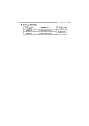
B. Memory Capacity DIMM Socket Location DIMMA1 DIMMA2 DDR3 Module 512MB/1GB/2GB/4GB 512MB/1GB/2GB/4GB Viotech 3200+ Total Memory Size Max is 8GB. 7
B. Memory Capacity DIMM Socket Location DIMMA1 DIMMA2 DDR3 Module 512MB/1GB/2GB/4GB 512MB/1GB/2GB/4GB Viotech 3200+ Total Memory Size Max is 8GB. 7
Setup Manual
Page 10
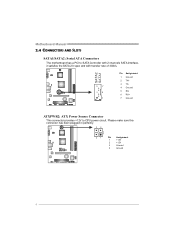
Please make sure this connector has been plugged in perfectly. 32 4 1 Pin Assignment 1 +12V 2 +12V 3 Ground 4 Ground 8 SATA2 SATA1 Pin Assignment 1 Ground 2 TX+ 3 TX- 7 4 Ground 4 5 RX- 6 RX+ 1 7 Ground ATXPWR2: ATX Power Source Connector This connector provides +12V to SATA Controller with 2 channels SATA interface, it satisfies the SATA 2.0 spec and with transfer rate of 3Gb/s. Motherboard Manual 2.4 CONNECTORS AND SLOTS SATA1/SATA2: Serial ATA Connectors The motherboard has a PCI to CPU power circuit.
Please make sure this connector has been plugged in perfectly. 32 4 1 Pin Assignment 1 +12V 2 +12V 3 Ground 4 Ground 8 SATA2 SATA1 Pin Assignment 1 Ground 2 TX+ 3 TX- 7 4 Ground 4 5 RX- 6 RX+ 1 7 Ground ATXPWR2: ATX Power Source Connector This connector provides +12V to SATA Controller with 2 channels SATA interface, it satisfies the SATA 2.0 spec and with transfer rate of 3Gb/s. Motherboard Manual 2.4 CONNECTORS AND SLOTS SATA1/SATA2: Serial ATA Connectors The motherboard has a PCI to CPU power circuit.

Setup Manual
Page 11
PCI stands for expansion cards. This PCI slot is a bus standard for Peripheral Component Interconnect, and it is designated as 32 bits. Viotech 3200+ ATXPWR1: ATX Power Source Connector This connector allows user to connect 24-pin power connector on the ATX power supply. 12 24 1 13 Pin Assignment ...
PCI stands for expansion cards. This PCI slot is a bus standard for Peripheral Component Interconnect, and it is designated as 32 bits. Viotech 3200+ ATXPWR1: ATX Power Source Connector This connector allows user to connect 24-pin power connector on the ATX power supply. 12 24 1 13 Pin Assignment ...

Setup Manual
Page 12
Maximum theoretical realized bandwidth of 4GB/s simultaneously per direction, for an aggregate of 8GB/s totally. PEX16_1 10 PCI-Express 2.0 compliant (x8-Lane only). - Motherboard Manual PEX16_1: PCI-Express x16 Slot -
Maximum theoretical realized bandwidth of 4GB/s simultaneously per direction, for an aggregate of 8GB/s totally. PEX16_1 10 PCI-Express 2.0 compliant (x8-Lane only). - Motherboard Manual PEX16_1: PCI-Express x16 Slot -

Setup Manual
Page 13
... drive 13 LED 14 Reset button 15 16 Assignment N/A N/A N/A Power LED (+) Power LED (+) Power LED (-) Power button Ground Function N/A N/A Power LED Power-on button 11 Viotech 3200+ CHAPTER 3: HEADERS & JUMPERS SETUP 3.1 HOW TO SETUP JUMPERS The illustration shows how to connect the PC case's front panel switch functions. It allows user to...
... drive 13 LED 14 Reset button 15 16 Assignment N/A N/A N/A Power LED (+) Power LED (+) Power LED (-) Power button Ground Function N/A N/A Power LED Power-on button 11 Viotech 3200+ CHAPTER 3: HEADERS & JUMPERS SETUP 3.1 HOW TO SETUP JUMPERS The illustration shows how to connect the PC case's front panel switch functions. It allows user to...

Setup Manual
Page 14
JUSBV2: +5V for USB ports at front panel (F_USB1/F_USB2). JUS B V 2 1 3 JUSBV1 1 3 Pin 1-2 close 1 3 Pin 2-3 close Note: In order to connect additional USB cable on Pin 2-3 individually. 12 Pin 2-3 Close: JUSBV1: +5V STB for USB ports at USB3/RJ45USB1. JUSBV2: +5V STB for USB ports at front panel (F_USB1/F_USB2). Motherboard Manual F_USB1/F_USB2: Headers for USB 2.0 Ports at Front Panel This motherboard provides 2 USB 2.0 headers, providing user to support this function "Power-On system via USB device," user should place "JUSBV1/ JUSBV2" jumper cap on the PC front panel, ...
JUSBV2: +5V for USB ports at front panel (F_USB1/F_USB2). JUS B V 2 1 3 JUSBV1 1 3 Pin 1-2 close 1 3 Pin 2-3 close Note: In order to connect additional USB cable on Pin 2-3 individually. 12 Pin 2-3 Close: JUSBV1: +5V STB for USB ports at USB3/RJ45USB1. JUSBV2: +5V STB for USB ports at front panel (F_USB1/F_USB2). Motherboard Manual F_USB1/F_USB2: Headers for USB 2.0 Ports at Front Panel This motherboard provides 2 USB 2.0 headers, providing user to support this function "Power-On system via USB device," user should place "JUSBV1/ JUSBV2" jumper cap on the PC front panel, ...

Setup Manual
Page 15
... the jumper to "Pin 1-2 close ". 3. Load Optimal Defaults and save settings in 10 Jack Sense 1 9 JCMOS1: Clear CMOS Header Placing the jumper on the AC. 6. Viotech 3200+ F_AUDIO1: Front Panel Audio Header This header allows user to connect the front audio output cable with the PC front panel. 2 10 Pin Assignment 1 Mic...
... the jumper to "Pin 1-2 close ". 3. Load Optimal Defaults and save settings in 10 Jack Sense 1 9 JCMOS1: Clear CMOS Header Placing the jumper on the AC. 6. Viotech 3200+ F_AUDIO1: Front Panel Audio Header This header allows user to connect the front audio output cable with the PC front panel. 2 10 Pin Assignment 1 Mic...

Setup Manual
Page 16
Motherboard Manual J_COM1: Serial port Connector The motherboard has a Serial Port Connector for connecting RS-232 Port. Assignment Carrier detect Received data Transmitted data Data terminal ready Signal ground Data set ready Request to send Clear to connector printer on the PC. Pin 1 2 3 4 5 6 7 2 10 8 9 10 1 9 J_PRINT1: Printer Port Connector This header allows you to send Ring indicator NC Pin Assignment 1 -Strobe 2 -ALF 3 Data 0 4 -Error 5 Data 1 6 -Init 7 Data 2 8 -Scltin 9 Data 3 10 Ground 11 Data 4 12 Ground 13 Data 5 2 26 1 25 ...
Motherboard Manual J_COM1: Serial port Connector The motherboard has a Serial Port Connector for connecting RS-232 Port. Assignment Carrier detect Received data Transmitted data Data terminal ready Signal ground Data set ready Request to send Clear to connector printer on the PC. Pin 1 2 3 4 5 6 7 2 10 8 9 10 1 9 J_PRINT1: Printer Port Connector This header allows you to send Ring indicator NC Pin Assignment 1 -Strobe 2 -ALF 3 Data 0 4 -Error 5 Data 1 6 -Init 7 Data 2 8 -Scltin 9 Data 3 10 Ground 11 Data 4 12 Ground 13 Data 5 2 26 1 25 ...

Setup Manual
Page 17
... optical drive and install the driver for your motherboard and operating system. You will need Acrobat Reader to launch the installation program. CHAPTER 4: USEFUL HELP Viotech 3200+ 4.1 DRIVER INSTALLATION NOTE After you insert the Driver CD, please use file browser to locate and execute the file SETUP.EXE under your optical drive...
... optical drive and install the driver for your motherboard and operating system. You will need Acrobat Reader to launch the installation program. CHAPTER 4: USEFUL HELP Viotech 3200+ 4.1 DRIVER INSTALLATION NOTE After you insert the Driver CD, please use file browser to locate and execute the file SETUP.EXE under your optical drive...

Setup Manual
Page 18
CPU fan is fulfilling with the CPU surface. 2. After confirmed, please follow steps below to avoid a damage of the CPU, and the system may not power on again. Wait for seconds. 3. Wait for seconds. 3. When the CPU is placed evenly with the CPU speed. The CPU cooler surface is over heated, the motherboard will shutdown automatically to relief the CPU 0protection function. 1. Power on system for seconds. 2. CPU fan speed is rotated normally. 3. Remove the power cord from power supply for minutes, that means the CPU protection function has been activated. Plug...
CPU fan is fulfilling with the CPU surface. 2. After confirmed, please follow steps below to avoid a damage of the CPU, and the system may not power on again. Wait for seconds. 3. Wait for seconds. 3. When the CPU is placed evenly with the CPU speed. The CPU cooler surface is over heated, the motherboard will shutdown automatically to relief the CPU 0protection function. 1. Power on system for seconds. 2. CPU fan speed is rotated normally. 3. Remove the power cord from power supply for minutes, that means the CPU protection function has been activated. Plug...

Setup Manual
Page 19
... even pressure on both ends are plugged in the system. 1. Make sure both ends of breaking down at any time. fails to disk controller board. Viotech 3200+ 5.3 TROUBLESHOOTING Probable Solution 1. There is in the standard CMOS setup. Check cable running . All hard disks are running from disk to boot from a hard disk...
... even pressure on both ends are plugged in the system. 1. Make sure both ends of breaking down at any time. fails to disk controller board. Viotech 3200+ 5.3 TROUBLESHOOTING Probable Solution 1. There is in the standard CMOS setup. Check cable running . All hard disks are running from disk to boot from a hard disk...