
Installation Instructions
Page 1
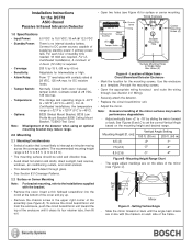
...;C to the installations supplied with the bracket. • Remove the cover. Use the enclosure as a template. Note: Misalignment of the detector when using an optional mounting bracket may lead to DC power sources capable of 4 hours (72 mAh) is 6.5 ft. Mounting Height ...; Open two holes (see Section 3.0 Wiring). • Securely attach the detector. • Replace the circuit board/mirror unit. • Adjust the mirror. Installation Instructions for the DS778 ASIC-Based Passive Infrared Intrusion Detector 1.0 Specifications • Input Power: 6.0 VDC to -18° by...
...;C to the installations supplied with the bracket. • Remove the cover. Use the enclosure as a template. Note: Misalignment of the detector when using an optional mounting bracket may lead to DC power sources capable of 4 hours (72 mAh) is 6.5 ft. Mounting Height ...; Open two holes (see Section 3.0 Wiring). • Securely attach the detector. • Replace the circuit board/mirror unit. • Adjust the mirror. Installation Instructions for the DS778 ASIC-Based Passive Infrared Intrusion Detector 1.0 Specifications • Input Power: 6.0 VDC to -18° by...

Installation Instructions
Page 2
...with capacitive or inductive loads. • 6 & 7: Normally Closed Tamper Contacts, rated 28 VDC, 125 mA. 4.0 Configuration Switches • Configure the detector using the appropriate switch settings (see Figure F). - 1 2 3 + NO C NC T T O PEN Configuration Switches Noise Voltage LED Tamper Switch... and 3 OFF = High 2 OFF and 3 ON = Intermediate 2 ON and 3 ON = Not Recommended Figure F - Page 2 © 2004 Bosch Security Systems DS778 Installation Instructions Do not use in normal condition (no smaller than #22 AWG (0.8 mm) wire pair. • 3 (NO), 4 (C), 5 (NC): Relay ...
...with capacitive or inductive loads. • 6 & 7: Normally Closed Tamper Contacts, rated 28 VDC, 125 mA. 4.0 Configuration Switches • Configure the detector using the appropriate switch settings (see Figure F). - 1 2 3 + NO C NC T T O PEN Configuration Switches Noise Voltage LED Tamper Switch... and 3 OFF = High 2 OFF and 3 ON = Intermediate 2 ON and 3 ON = Not Recommended Figure F - Page 2 © 2004 Bosch Security Systems DS778 Installation Instructions Do not use in normal condition (no smaller than #22 AWG (0.8 mm) wire pair. • 3 (NO), 4 (C), 5 (NC): Relay ...