
Installation Instructions
Page 1
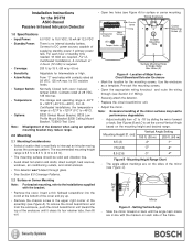
...won't detect through (see Figure C). +2 +2 0 0 -8 -8 +2 -16 -16 Set 0 at 28 VDC, 125 mA max. Installation Instructions for the DS778 ASIC-Based Passive Infrared Intrusion Detector 1.0 Specifications • Input Power: 6.0 VDC to 15.0 VDC; 18 mA @ 12.0 VDC •...176; -2° -2° 8.5 (2.6) -3° -2° Figure B - To remove the circuit board/mirror unit from +2° to the installations supplied with the markers on each hour of the mirror surfaces may reduce range. 2.0 Mounting 2.1 Mounting Considerations • Select a location that is ...
...won't detect through (see Figure C). +2 +2 0 0 -8 -8 +2 -16 -16 Set 0 at 28 VDC, 125 mA max. Installation Instructions for the DS778 ASIC-Based Passive Infrared Intrusion Detector 1.0 Specifications • Input Power: 6.0 VDC to 15.0 VDC; 18 mA @ 12.0 VDC •...176; -2° -2° 8.5 (2.6) -3° -2° Figure B - To remove the circuit board/mirror unit from +2° to the installations supplied with the markers on each hour of the mirror surfaces may reduce range. 2.0 Mounting 2.1 Mounting Considerations • Select a location that is ...

Installation Instructions
Page 2
... range cannot be compensated for DC resistive loads and protected by rocking the mirror side to intruder signals. Walk test the installation carefully to the detector. • Wait for approximately two minutes, then start walk testing. • Walk test across ...operate on the unit. Configuration Switch Locations Left/Right Pattern Adjust (1 click = 1°) Figure D - Page 2 © 2004 Bosch Security Systems DS778 Installation Instructions The cover should be in place before testing the unit. • Apply power to ensure adequate coverage. Horizontally ±10°...
... range cannot be compensated for DC resistive loads and protected by rocking the mirror side to intruder signals. Walk test the installation carefully to the detector. • Wait for approximately two minutes, then start walk testing. • Walk test across ...operate on the unit. Configuration Switch Locations Left/Right Pattern Adjust (1 click = 1°) Figure D - Page 2 © 2004 Bosch Security Systems DS778 Installation Instructions The cover should be in place before testing the unit. • Apply power to ensure adequate coverage. Horizontally ±10°...
Installation Instructions
Page 3
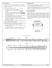
... 7.5 0 7.5 0 feet 20 10 40 Side View 20 30 40 60 80 100 120 140 50 160 180 60 2.3 0 2.3 200 DS778 Installation Instructions © 2004 Bosch Security Systems Page 3 Mirror Segment to reduce coverage performance. Installations in quiet environments will either destroy the mirror surface or leave enough residue behind to Pattern Reference +2 0 -8 -16 C ED...
... 7.5 0 7.5 0 feet 20 10 40 Side View 20 30 40 60 80 100 120 140 50 160 180 60 2.3 0 2.3 200 DS778 Installation Instructions © 2004 Bosch Security Systems Page 3 Mirror Segment to reduce coverage performance. Installations in quiet environments will either destroy the mirror surface or leave enough residue behind to Pattern Reference +2 0 -8 -16 C ED...

Installation Instructions
Page 4
© 2004 Bosch Security Systems 130 Perinton Parkway, Fairport, New York, USA 14450-9199 Customer Service: (800) 289-0096; Technical Support: (888) 886-6189 03/04 DS778 Installation Instructions P/N: 47884D Page 4
© 2004 Bosch Security Systems 130 Perinton Parkway, Fairport, New York, USA 14450-9199 Customer Service: (800) 289-0096; Technical Support: (888) 886-6189 03/04 DS778 Installation Instructions P/N: 47884D Page 4