
Installation Instructions
Page 1
... Base Enclosure Release Tabs Enclosure The Cover remains attached to the Enclosure Cover • Remove the base from the enclosure by Bosch Security Systems can void the user's authority to operate the equipment. Recommended mounting height range is 8 to 18 feet (2.4 to...8226; Route wiring as an air return for Intermediate and High. • Alarm Relay: Silent-operating Form "C" relay. DS9360 TriTech Ceiling Mount PIR/ Microwave Intrusion Detector 1.0 Specifications • Dimensions (HxDia): 3.5 in operation within its field-of-view. • Eliminate interference from nearby ...
... Base Enclosure Release Tabs Enclosure The Cover remains attached to the Enclosure Cover • Remove the base from the enclosure by Bosch Security Systems can void the user's authority to operate the equipment. Recommended mounting height range is 8 to 18 feet (2.4 to...8226; Route wiring as an air return for Intermediate and High. • Alarm Relay: Silent-operating Form "C" relay. DS9360 TriTech Ceiling Mount PIR/ Microwave Intrusion Detector 1.0 Specifications • Dimensions (HxDia): 3.5 in operation within its field-of-view. • Eliminate interference from nearby ...

Installation Instructions
Page 2
Note: Hint: The DS9360 base will not indicate activation of the second technology by the tabs, snap the new module into place. Do not coil excess wiring CAUTION inside detector. POWER ALARM TAMPER -+ REAR WIRE ENTRANCE TERMINAL STRIP 1 WIRE TIE-DOWNS (2) MOUNTING SLOTS (4) INTERFACE PINS 8 Mounting Base Anti-vandal Screw Hole Required ... power source. • Terminals 3 (NO), 4 (C), & 5 (NC): Alarm relay contacts rated 125 mA, 28 VDC maximum for Normally Closed circuits. Shorts to ground (-) when the detector is recommended. Page 2 © 2011 Bosch Security Systems, Inc.
Note: Hint: The DS9360 base will not indicate activation of the second technology by the tabs, snap the new module into place. Do not coil excess wiring CAUTION inside detector. POWER ALARM TAMPER -+ REAR WIRE ENTRANCE TERMINAL STRIP 1 WIRE TIE-DOWNS (2) MOUNTING SLOTS (4) INTERFACE PINS 8 Mounting Base Anti-vandal Screw Hole Required ... power source. • Terminals 3 (NO), 4 (C), & 5 (NC): Alarm relay contacts rated 125 mA, 28 VDC maximum for Normally Closed circuits. Shorts to ground (-) when the detector is recommended. Page 2 © 2011 Bosch Security Systems, Inc.
Installation Instructions
Page 3
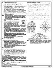
... least once a year, the range and coverage should be verified. DS9360 Installation Guide © 2011 Bosch Security Systems, Inc. Continue walk testing (waiting 1 minute after removing/replacing the cover so the microwave portion of the detector. If the PIR or microwave subsystem fails, the red LED will flash... is checked approximately every 6 hours. This ensures an alarm output prior to the Bosch Security Systems, Inc. Page 3 Do not adjust the microwave range higher than required. Start walking from the detector. • To block out a particular zone or group of zones, peel off...
... least once a year, the range and coverage should be verified. DS9360 Installation Guide © 2011 Bosch Security Systems, Inc. Continue walk testing (waiting 1 minute after removing/replacing the cover so the microwave portion of the detector. If the PIR or microwave subsystem fails, the red LED will flash... is checked approximately every 6 hours. This ensures an alarm output prior to the Bosch Security Systems, Inc. Page 3 Do not adjust the microwave range higher than required. Start walking from the detector. • To block out a particular zone or group of zones, peel off...