

Installation Instructions
Page 3
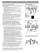
...orientation on end of a power supply cord. Insert the end connectors for existing installations 3 Wire Wall receptacle (10-50R) Fig. 8 NOTE: Range is shipped from the frame of the appliance with the eyelet to the terminal block. Make sure all screws are loosened or removed. 3. for... see Figs. 9, 10 & 11). 2. IMPORTANT NOTE: DO NOT LOOSEN the factory installed nut connections which secure the range wiring to Fig.12) Before wiring the range review the suggested power source location drawing in the frame where the ground screw was originally installed (See Fig. 12). 5. ...
...orientation on end of a power supply cord. Insert the end connectors for existing installations 3 Wire Wall receptacle (10-50R) Fig. 8 NOTE: Range is shipped from the frame of the appliance with the eyelet to the terminal block. Make sure all screws are loosened or removed. 3. for... see Figs. 9, 10 & 11). 2. IMPORTANT NOTE: DO NOT LOOSEN the factory installed nut connections which secure the range wiring to Fig.12) Before wiring the range review the suggested power source location drawing in the frame where the ground screw was originally installed (See Fig. 12). 5. ...
Installation Instructions
Page 4
...for any reason, a separate ground wire must be set at approximately 22in./ lbs. follow Steps 1 thru 5 below . 4 - Before wiring the range, review the suggested power source location drawings in ./lbs. Be sure to an adequate ground source. 4c. 3 & 4-WIRE PERMANENT WIRE CONNECTIONS. 3 - ...electrical connection may occur if these 3 nuts are tightened securely and replace the rear access cover (See Fig. 9). CAREFULLY SLIDE RANGE INTO FINAL LOCATION. Grounding Instructions (3-Wire Connections only): A ground strap is connected to release the factory installed copper ground strap ...
...for any reason, a separate ground wire must be set at approximately 22in./ lbs. follow Steps 1 thru 5 below . 4 - Before wiring the range, review the suggested power source location drawings in ./lbs. Be sure to an adequate ground source. 4c. 3 & 4-WIRE PERMANENT WIRE CONNECTIONS. 3 - ...electrical connection may occur if these 3 nuts are tightened securely and replace the rear access cover (See Fig. 9). CAREFULLY SLIDE RANGE INTO FINAL LOCATION. Grounding Instructions (3-Wire Connections only): A ground strap is connected to release the factory installed copper ground strap ...


