User Manual
Page 4
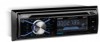
... ensure than the front part of the main unit will remain into the vehicle dash opening. 2. Make wiring connections, as illustrated, to secure the rear part of the chassis, as illustrated in the "Wiring Diagram." 5. BRACKET KEY PLASTIC TRIM OUT BRACKET KEY If you begin, disconnect the battery negative terminal. 2. Install the plastic...
... ensure than the front part of the main unit will remain into the vehicle dash opening. 2. Make wiring connections, as illustrated, to secure the rear part of the chassis, as illustrated in the "Wiring Diagram." 5. BRACKET KEY PLASTIC TRIM OUT BRACKET KEY If you begin, disconnect the battery negative terminal. 2. Install the plastic...

User Manual
Page 5
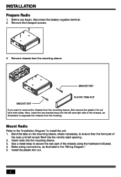
... 200mA. The maximum current of the auto antenna is complete. - Green/Black - 3 INSTALLATION (CONT.) INSTALLATION DIAGRAM HEX NUT PLAIN WASHER TAPPING SCREW DASH BOARD METAL MOUNTING STRAP CONSOLE MOUNTING SLEEVE HEX BOLT - Wiring Connections WIRING DIAGRAM Radio Antenna Socket White: Front Left CH RCA Output Red: Front Right CH RCA Output Red: Rear Right...
... 200mA. The maximum current of the auto antenna is complete. - Green/Black - 3 INSTALLATION (CONT.) INSTALLATION DIAGRAM HEX NUT PLAIN WASHER TAPPING SCREW DASH BOARD METAL MOUNTING STRAP CONSOLE MOUNTING SLEEVE HEX BOLT - Wiring Connections WIRING DIAGRAM Radio Antenna Socket White: Front Left CH RCA Output Red: Front Right CH RCA Output Red: Rear Right...


