User Manual
Page 2
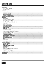
CONTENTS Precautions...1 Lithium Battery Cell Warnings ...1 Take Precaution...1 Installation ...2-3 Installation Procedures ...2 Installation Opening...2 Wiring Connections...3 Remove of the Main Unit ...3 Control Panel Button Locations ...4 Operation ...4-5 Power / SRC ...4 Adjust Menu Options (SRC) ...4 Change the Source (SRC) ...4 Store/... Navigation ...5 Mute ...5 AUX In Jack ...5 Reset System (RESET) ...5 Bluetooth Operation...6 Pair and Connect ...6 Make a Call ...6 Redial Last Dialed Number ...6 Answer a Call...6 End a Call ...6 Switch Audio Between Car and Phone 6 Adjust Talk Volume...
CONTENTS Precautions...1 Lithium Battery Cell Warnings ...1 Take Precaution...1 Installation ...2-3 Installation Procedures ...2 Installation Opening...2 Wiring Connections...3 Remove of the Main Unit ...3 Control Panel Button Locations ...4 Operation ...4-5 Power / SRC ...4 Adjust Menu Options (SRC) ...4 Change the Source (SRC) ...4 Store/... Navigation ...5 Mute ...5 AUX In Jack ...5 Reset System (RESET) ...5 Bluetooth Operation...6 Pair and Connect ...6 Make a Call ...6 Redial Last Dialed Number ...6 Answer a Call...6 End a Call ...6 Switch Audio Between Car and Phone 6 Adjust Talk Volume...

User Manual
Page 4
MOUNTING SLEEVE Insert mounting collar into the dashboard and bend the mounting tabs out with the mounting collar( not projecting outward). 2 INSTALLATION Installation Procedures First complete the electrical connections and then check for correctness. Installation Opening 2.05 inch 7.20 inch This unit can be installed in any dashboard Having an opening as shown above . Make sure that lock lever is flush with a screwdriver.
MOUNTING SLEEVE Insert mounting collar into the dashboard and bend the mounting tabs out with the mounting collar( not projecting outward). 2 INSTALLATION Installation Procedures First complete the electrical connections and then check for correctness. Installation Opening 2.05 inch 7.20 inch This unit can be installed in any dashboard Having an opening as shown above . Make sure that lock lever is flush with a screwdriver.
User Manual
Page 5
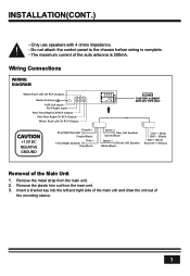
... chassis before wiring is 200mA. Green + Rear Left Speaker Green/Black - White + Front Left Speaker White/Black - Remove the metal strap from the main unit. 3. INSTALLATION(CONT.) - ACC + (Red) GND - (Black) ANT + (Blue) Power B + (Yellow) Removal of the mounting sleeve. 3 Insert a bracket key into the left and right side of the...
... chassis before wiring is 200mA. Green + Rear Left Speaker Green/Black - White + Front Left Speaker White/Black - Remove the metal strap from the main unit. 3. INSTALLATION(CONT.) - ACC + (Red) GND - (Black) ANT + (Blue) Power B + (Yellow) Removal of the mounting sleeve. 3 Insert a bracket key into the left and right side of the...


