

Service Manual
Page 2
...order any necessary spare parts. CHAPTER III. GENERAL DESCRIPTION INSTALLATION THEORY OF OPERATION DISASSEMBLY/REASSEMBLY AND LUBRICATION MAINTENANCE MODE ERROR INDICATION AND TROUBLESHOOTING APPENDICES Circuit Diagrams This manual describes the model and its versions to be able to understand equipment function, to change depending upon ... CHAPTER I. CHAPTER II. This manual is always in best condition for major countries. It includes information required for field troubleshooting and repair-disassembly, reassembly, and adjustment-so that the facsimile equipment is made up of the...
...order any necessary spare parts. CHAPTER III. GENERAL DESCRIPTION INSTALLATION THEORY OF OPERATION DISASSEMBLY/REASSEMBLY AND LUBRICATION MAINTENANCE MODE ERROR INDICATION AND TROUBLESHOOTING APPENDICES Circuit Diagrams This manual describes the model and its versions to be able to understand equipment function, to change depending upon ... CHAPTER I. CHAPTER II. This manual is always in best condition for major countries. It includes information required for field troubleshooting and repair-disassembly, reassembly, and adjustment-so that the facsimile equipment is made up of the...
Service Manual
Page 139
ERROR INDICATION AND TROUBLESHOOTING CHAPTER VI.
ERROR INDICATION AND TROUBLESHOOTING CHAPTER VI.
Service Manual
Page 140
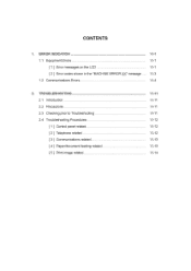
ERROR INDICATION 1.1 Equipment Errors [ 1 ] Error messages on the LCD [ 2 ] Error codes shown in the "MACHINE ERROR XX" message 1.2 Communications Errors VI-1 VI-1 VI-1 VI-3 VI-4 2. CONTENTS 1. TROUBLESHOOTING 2.1 Introduction 2.2 Precautions 2.3 Checking prior to Troubleshooting 2.4 Troubleshooting Procedures [ 1 ] Control panel related [ 2 ] Telephone related [ 3 ] Communications related [ 4 ] Paper/document feeding related [ 5 ] Print-image related VI-11 VI-11 VI-11 VI-11 VI-12 VI-12 VI-12 VI-13 VI-13 VI-14
ERROR INDICATION 1.1 Equipment Errors [ 1 ] Error messages on the LCD [ 2 ] Error codes shown in the "MACHINE ERROR XX" message 1.2 Communications Errors VI-1 VI-1 VI-1 VI-3 VI-4 2. CONTENTS 1. TROUBLESHOOTING 2.1 Introduction 2.2 Precautions 2.3 Checking prior to Troubleshooting 2.4 Troubleshooting Procedures [ 1 ] Control panel related [ 2 ] Telephone related [ 3 ] Communications related [ 4 ] Paper/document feeding related [ 5 ] Print-image related VI-11 VI-11 VI-11 VI-11 VI-12 VI-12 VI-12 VI-13 VI-13 VI-14
Service Manual
Page 151
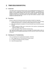
...help service personnel pinpoint and repair other defective elements if he/she analyzes and examines them with the facsimile equipment. Also record the troubleshooting procedure so that : (1) Each voltage level on AC input lines and DC lines is impossible to anticipate all of the possible ... connectors, do not pull the lead wires but hold the connector housings. (3) • Before handling the PCBs, touch a metal portion of the troubleshooting procedures to be followed if an error or malfunction occurs with extra care. 2. It is correct. (2) All cables and harnesses are blown. After ...
...help service personnel pinpoint and repair other defective elements if he/she analyzes and examines them with the facsimile equipment. Also record the troubleshooting procedure so that : (1) Each voltage level on AC input lines and DC lines is impossible to anticipate all of the possible ... connectors, do not pull the lead wires but hold the connector housings. (3) • Before handling the PCBs, touch a metal portion of the troubleshooting procedures to be followed if an error or malfunction occurs with extra care. 2. It is correct. (2) All cables and harnesses are blown. After ...
Service Manual
Page 152
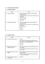
... PCB • Main-panel harness between the main PCB and the control panel PCB • Interfaces between tone and pulse. • Main PCB VI -12 2.4 Troubleshooting Procedures [ 1 ] Control panel related Trouble (1) LCD shows nothing. (2) Control panel inoperative. Check: • FPC key • Control panel PCB by using the maintenance-mode function...
... PCB • Main-panel harness between the main PCB and the control panel PCB • Interfaces between tone and pulse. • Main PCB VI -12 2.4 Troubleshooting Procedures [ 1 ] Control panel related Trouble (1) LCD shows nothing. (2) Control panel inoperative. Check: • FPC key • Control panel PCB by using the maintenance-mode function...


