
Parts List
Page 1
FACSIMILE EQUIPMENT PARTS REFERENCE LIST MODEL: FAX-8650P (For Germany / United Kingdom / France / Norway / Belgium / Netherlands / Switzerland / Sweden)
FACSIMILE EQUIPMENT PARTS REFERENCE LIST MODEL: FAX-8650P (For Germany / United Kingdom / France / Norway / Belgium / Netherlands / Switzerland / Sweden)

Service Manual
Page 7
drum unit & toner cartridge) In package Approx. 7.2 kg Approx. 8.5 kg Approx. 12 kg 1.2 Components The equipment consists of the following major components: I - 1 *1 Provided on the FAX3750/MFC7750. *2 Provided on the FAX-8650P. Weight: Machine proper Machine (incl. 1. EQUIPMENT OUTLINE 1.1 External Appearance and Weight The figure below shows the equipment appearance and approximate dimensions.
drum unit & toner cartridge) In package Approx. 7.2 kg Approx. 8.5 kg Approx. 12 kg 1.2 Components The equipment consists of the following major components: I - 1 *1 Provided on the FAX3750/MFC7750. *2 Provided on the FAX-8650P. Weight: Machine proper Machine (incl. 1. EQUIPMENT OUTLINE 1.1 External Appearance and Weight The figure below shows the equipment appearance and approximate dimensions.

Service Manual
Page 8
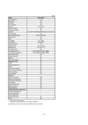
... Interface/Interface Cable SCANNER Color/Mono dpi Gray Scale Twain Formats (Import) Formats (Export) ADF (pages) OCR COPY dpi Collating Reduction/Enlargement Sorting FAX Modem/Speed (bps) CCITT Group Coding Method Error Correction Mode (ECM) Transmission Speed (sec) Gray Scale Super Fine Smoothing Multi-Resolution TX Input/...MAX/PDF 20 *2 Yes (Xerox Textbridge) Yes 300 x 600 99 50, 75, 87, 93, 100, 120, 125, 150, 200% Yes Yes ROCKWELL F288R (33.6K FAX Only) Super G3 MH/MR/MMR Yes 3 64 Yes Yes Yes 8.5" x 8.5" 16 x 2 Yes No *1 Optional CD-ROM required. *2 30 pages under the following conditions:...
... Interface/Interface Cable SCANNER Color/Mono dpi Gray Scale Twain Formats (Import) Formats (Export) ADF (pages) OCR COPY dpi Collating Reduction/Enlargement Sorting FAX Modem/Speed (bps) CCITT Group Coding Method Error Correction Mode (ECM) Transmission Speed (sec) Gray Scale Super Fine Smoothing Multi-Resolution TX Input/...MAX/PDF 20 *2 Yes (Xerox Textbridge) Yes 300 x 600 99 50, 75, 87, 93, 100, 120, 125, 150, 200% Yes Yes ROCKWELL F288R (33.6K FAX Only) Super G3 MH/MR/MMR Yes 3 64 Yes Yes Yes 8.5" x 8.5" 16 x 2 Yes No *1 Optional CD-ROM required. *2 30 pages under the following conditions:...

Service Manual
Page 9
...Interface Cable SCANNER Color/Mono dpi Gray Scale Twain Formats (Import) Formats (Export) ADF (pages) OCR COPY dpi Collating Reduction/Enlargement Sorting FAX Modem/Speed (bps) CCITT Group Coding Method Error Correction Mode (ECM) Transmission Speed (sec) Gray Scale Super Fine Smoothing Multi-Resolution ...TX Input/Output Width LCD Size Handset Duplex Speaker Phone (1/2) FAX-8650P White (1138) Yes YL (VA) 6 ppm 600 x 600 200 PCL4 Windows GDI (600 x 600) 2 MB 1.2 MB 24-bit MAP (PCL4Comp) ...
...Interface Cable SCANNER Color/Mono dpi Gray Scale Twain Formats (Import) Formats (Export) ADF (pages) OCR COPY dpi Collating Reduction/Enlargement Sorting FAX Modem/Speed (bps) CCITT Group Coding Method Error Correction Mode (ECM) Transmission Speed (sec) Gray Scale Super Fine Smoothing Multi-Resolution ...TX Input/Output Width LCD Size Handset Duplex Speaker Phone (1/2) FAX-8650P White (1138) Yes YL (VA) 6 ppm 600 x 600 200 PCL4 Windows GDI (600 x 600) 2 MB 1.2 MB 24-bit MAP (PCL4Comp) ...

Service Manual
Page 10
...4 MB Memory (Opt Upgrade) Simultaneous Operation No Available with option *1 [ (PRINTER/FAX, PRINTER/SCAN, PRINTER/COPY) ] Data Modem Bundled Software Applications No Available with option *1 PC-FAX (Send/Receive) [SMSI] Scanner Application [Brother] Viewer Application [Visioneer] Network Application No Class 1 No *1 Optional CD-ROM required....) Yes Yes No No No No No Yes No No No Yes Yes (2/2) Yes 4 MB No Yes (PRINTER/FAX, PRINTER/SCAN, PRINTER/COPY) No Yes SMSI Brother Visioneer Yes I - 4 Model FAX3750 One-touch Dial 12 x 2 Speed Dial 100 Tel-Index Yes Chain Dialing ...
...4 MB Memory (Opt Upgrade) Simultaneous Operation No Available with option *1 [ (PRINTER/FAX, PRINTER/SCAN, PRINTER/COPY) ] Data Modem Bundled Software Applications No Available with option *1 PC-FAX (Send/Receive) [SMSI] Scanner Application [Brother] Viewer Application [Visioneer] Network Application No Class 1 No *1 Optional CD-ROM required....) Yes Yes No No No No No Yes No No No Yes Yes (2/2) Yes 4 MB No Yes (PRINTER/FAX, PRINTER/SCAN, PRINTER/COPY) No Yes SMSI Brother Visioneer Yes I - 4 Model FAX3750 One-touch Dial 12 x 2 Speed Dial 100 Tel-Index Yes Chain Dialing ...
Service Manual
Page 11
...5 (2/2) Model MFC-8650P One-touch Dial 12 x 2 Speed Dial 100 Tel-Index Yes Chain Dialing Yes Contrast SL/Auto/SD FAX/TEL Switch Yes Distinctive Ringing No Caller ID Yes (U.K./French/Belgium/Netherlands versions only) TAD Interface Yes Next FAX Reservation Yes, Dual ... Memory Backup Yes Bundled Software Applications PC-FAX (Send/Receive) Scanner Application Viewer Application Network Application No Class 1 Yes *1 Optional CD-ROM required. *4 According to the Brother chart in standard mode, MMR. Specifications enclosed in ...
...5 (2/2) Model MFC-8650P One-touch Dial 12 x 2 Speed Dial 100 Tel-Index Yes Chain Dialing Yes Contrast SL/Auto/SD FAX/TEL Switch Yes Distinctive Ringing No Caller ID Yes (U.K./French/Belgium/Netherlands versions only) TAD Interface Yes Next FAX Reservation Yes, Dual ... Memory Backup Yes Bundled Software Applications PC-FAX (Send/Receive) Scanner Application Viewer Application Network Application No Class 1 Yes *1 Optional CD-ROM required. *4 According to the Brother chart in standard mode, MMR. Specifications enclosed in ...
Service Manual
Page 18
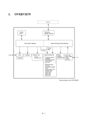
III - 1 OVERVIEW *Not provided on the FAX-8650P. 1.
III - 1 OVERVIEW *Not provided on the FAX-8650P. 1.

Service Manual
Page 27
... Main PCB Main PCB High-voltage power supply PCB Toner sensor PCB Toner sensor PCB Heat-fixing unit Hook switch PCB* *Not provided on the FAX-8650P. • Document front sensor which detects the presence of documents. • Document rear sensor which detects the leading and trailing edges of pages to tell...
... Main PCB Main PCB High-voltage power supply PCB Toner sensor PCB Toner sensor PCB Heat-fixing unit Hook switch PCB* *Not provided on the FAX-8650P. • Document front sensor which detects the presence of documents. • Document rear sensor which detects the leading and trailing edges of pages to tell...

Service Manual
Page 28
Location of Sensors and Actuators III - 11 *Not provided on the FAX-8650P.
Location of Sensors and Actuators III - 11 *Not provided on the FAX-8650P.

Service Manual
Page 29
... thermister *4 On the high-voltage power supply PCB is the paper ejection sensor. *5 On the hook switch PCB is shown below. (NOTE 1) Provided on the FAX-8650P.) Configuration of Facsimile Equipment III - 12 CONTROL ELECTRONICS 3.1 Configuration The hardware configuration of the facsimile equipment is the hook switch. (Not provided on the...
... thermister *4 On the high-voltage power supply PCB is the paper ejection sensor. *5 On the hook switch PCB is shown below. (NOTE 1) Provided on the FAX-8650P.) Configuration of Facsimile Equipment III - 12 CONTROL ELECTRONICS 3.1 Configuration The hardware configuration of the facsimile equipment is the hook switch. (Not provided on the...

Service Manual
Page 30
3.2 Main PCB The main PCB, which is the nucleus controlling the entire operation of the equipment, consists of a FAX engine (ASIC), memories, MODEM, motor drive circuitry, sensor detection circuitry, and analog circuits for scanning, printing, and power transmission shifting. (Provided on the FAX-8650P) (Provided on the FAX3750/ MFC7750) EEPROM:Electrically Erasable Programmable Read-only Memory DRAM: Dynamic Random Access Memory Block Diagram of Main PCB III - 13
3.2 Main PCB The main PCB, which is the nucleus controlling the entire operation of the equipment, consists of a FAX engine (ASIC), memories, MODEM, motor drive circuitry, sensor detection circuitry, and analog circuits for scanning, printing, and power transmission shifting. (Provided on the FAX-8650P) (Provided on the FAX3750/ MFC7750) EEPROM:Electrically Erasable Programmable Read-only Memory DRAM: Dynamic Random Access Memory Block Diagram of Main PCB III - 13
Service Manual
Page 33
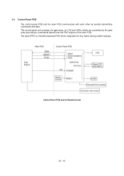
Control Panel PCB and its Related Circuit III - 16 The panel FPC is a flexible keyboard PCB which are controlled by serially transmitting commands and data. 3.4 Control Panel PCB The control panel PCB and the main PCB communicate with each other by the gate array according to commands issued from the FAX engine on the main PCB. The control panel unit consists of a gate array, an LCD and LEDs, which integrates the key matrix having rubber keytops.
Control Panel PCB and its Related Circuit III - 16 The panel FPC is a flexible keyboard PCB which are controlled by serially transmitting commands and data. 3.4 Control Panel PCB The control panel PCB and the main PCB communicate with each other by the gate array according to commands issued from the FAX engine on the main PCB. The control panel unit consists of a gate array, an LCD and LEDs, which integrates the key matrix having rubber keytops.
Service Manual
Page 37
... Cover ...IV-21 1.9 Handset Mount and Hook Switch PCB (for the FAX3750/MFC7750) Side Cover (for the FAX-8650P IV-24 1.10 Heat-fixing Unit, FU Lamp, and Paper Ejection Sensor Actuator IV-26 1.11 Laser Unit and Toner Sensor PCB IV-28 1.12 Bottom Plate IV-29 1.13 Low-voltage Power Supply...
... Cover ...IV-21 1.9 Handset Mount and Hook Switch PCB (for the FAX3750/MFC7750) Side Cover (for the FAX-8650P IV-24 1.10 Heat-fixing Unit, FU Lamp, and Paper Ejection Sensor Actuator IV-26 1.11 Laser Unit and Toner Sensor PCB IV-28 1.12 Bottom Plate IV-29 1.13 Low-voltage Power Supply...

Service Manual
Page 39
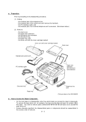
... equipment to the electricity charged in conductive sheets such as wires, PCBs, and covers. (7) Before handling the PCBs, touch a metal portion of the laser beam. WARNING For the FAX-8650P which has a Ni-MH battery on the main PCB, be put back in a short circuit, overcurrent flow, or fire. (9) Be sure to reinsert... cord from the document LF roller ASSY or ejection roller ASSY if at all possible. DISASSEMBLY/REASSEMBLY n Safety Precautions To prevent the creation of the laser printing unit, be sure to lose screws, washers, or other reflective objects in aluminum foil). IV - 1 1.
... equipment to the electricity charged in conductive sheets such as wires, PCBs, and covers. (7) Before handling the PCBs, touch a metal portion of the laser beam. WARNING For the FAX-8650P which has a Ni-MH battery on the main PCB, be put back in a short circuit, overcurrent flow, or fire. (9) Be sure to reinsert... cord from the document LF roller ASSY or ejection roller ASSY if at all possible. DISASSEMBLY/REASSEMBLY n Safety Precautions To prevent the creation of the laser printing unit, be sure to lose screws, washers, or other reflective objects in aluminum foil). IV - 1 1.
Service Manual
Page 41
.... (Not shown below.) (2) Remove - the modular jack of removal. the dust cover, - To remove the gear drive unit, for example, first find it on the FAX-8650P) n How to Access the Object Component • On the next page is a disassembly order flow which helps you access the object components.
.... (Not shown below.) (2) Remove - the modular jack of removal. the dust cover, - To remove the gear drive unit, for example, first find it on the FAX-8650P) n How to Access the Object Component • On the next page is a disassembly order flow which helps you access the object components.
Service Manual
Page 43
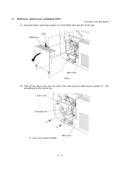
1.1 ROM Cover, Option Cover, and Battery ASSY* (*Provided on the FAX-8650P) (1) As shown below, push down section "a" of the ROM cover and tilt it to the rear. (2) Take off the option cover from the rear of the main cover by removing two screws "a." The grounding wire also comes free. IV - 5
1.1 ROM Cover, Option Cover, and Battery ASSY* (*Provided on the FAX-8650P) (1) As shown below, push down section "a" of the ROM cover and tilt it to the rear. (2) Take off the option cover from the rear of the main cover by removing two screws "a." The grounding wire also comes free. IV - 5

Service Manual
Page 44
...-MH battery), plug the power cord of the facsimile equipment into a power outlet, disconnect the battery harness from its supports and put it on the FAX-8650P) IV - 6 Disconnecting the battery harness with the battery harness being connected. Set a new battery ASSY, connect the battery harness to replace the battery ASSY but... ASSY while pulling the battery support of the main cover in the RAM. If you will lose the settings (e.g., calendar clock, voice messages, and received FAX data) stored in the direction of the arrow.
...-MH battery), plug the power cord of the facsimile equipment into a power outlet, disconnect the battery harness from its supports and put it on the FAX-8650P) IV - 6 Disconnecting the battery harness with the battery harness being connected. Set a new battery ASSY, connect the battery harness to replace the battery ASSY but... ASSY while pulling the battery support of the main cover in the RAM. If you will lose the settings (e.g., calendar clock, voice messages, and received FAX data) stored in the direction of the arrow.

Service Manual
Page 62
... handset mount* or side cover** so that it tilts over to the main PCB in the main cover. *For the FAX3750/MFC7750 **For the FAX-8650P For the FAX-8650P For the FAX3750/MFC7750 IV - 24 The hook switch harness* is connected to the left and its upper end works out of right and... the top cover. (3) Remove the two screws from the main cover. 1.9 Handset Mount and Hook Switch PCB (for the FAX3750/MFC7750) Side Cover (for the FAX-8650P) (1) Open the top cover. (2) Remove one of two screws from each of the bosses provided on the main cover.
... handset mount* or side cover** so that it tilts over to the main PCB in the main cover. *For the FAX3750/MFC7750 **For the FAX-8650P For the FAX-8650P For the FAX3750/MFC7750 IV - 24 The hook switch harness* is connected to the left and its upper end works out of right and... the top cover. (3) Remove the two screws from the main cover. 1.9 Handset Mount and Hook Switch PCB (for the FAX3750/MFC7750) Side Cover (for the FAX-8650P) (1) Open the top cover. (2) Remove one of two screws from each of the bosses provided on the main cover.
Service Manual
Page 70
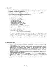
...and disconnect it from the low-voltage power supply PCB. (4) Disconnect the following harnesses from the main PCB: • Speaker harness (2-pin, P7) • Laser diode harness (5-pin, P6) • Toner sensor harness (4-pin, P5) • Polygon motor flat cable (5-pin, P4) • NCU harness 2 (6-...8226; Scanner motor harness (5-pin, P17) • Panel-main harness (6-pin, P21) (*2 Not provided on the FAX-8650P.) *1 The FAX-8650P has a Ni-MH battery ASSY. 1.14 Main PCB (1) For the FAX-8650P, take the battery ASSY*1 out of the supports at location "b" as shown on the next page. • For ...
...and disconnect it from the low-voltage power supply PCB. (4) Disconnect the following harnesses from the main PCB: • Speaker harness (2-pin, P7) • Laser diode harness (5-pin, P6) • Toner sensor harness (4-pin, P5) • Polygon motor flat cable (5-pin, P4) • NCU harness 2 (6-...8226; Scanner motor harness (5-pin, P17) • Panel-main harness (6-pin, P21) (*2 Not provided on the FAX-8650P.) *1 The FAX-8650P has a Ni-MH battery ASSY. 1.14 Main PCB (1) For the FAX-8650P, take the battery ASSY*1 out of the supports at location "b" as shown on the next page. • For ...

Service Manual
Page 71
*1 Provided on the FAX-8650P. *2 Not provided on the FAX-8650P. IV - 33
*1 Provided on the FAX-8650P. *2 Not provided on the FAX-8650P. IV - 33


