

Instruction Manual - Spanish
Page 7
... cutting pressure 63 9-14. Adjusting the spreader mounting positions ........ 59 9-8. CHANGING FUNCTIONS USING THE MEMORY SWITCHES 72 10-1.Memory switch table 73 11. LIST OF ERROR CODES 77 13. TROUBLESHOOTING 80 RH-981A
... cutting pressure 63 9-14. Adjusting the spreader mounting positions ........ 59 9-8. CHANGING FUNCTIONS USING THE MEMORY SWITCHES 72 10-1.Memory switch table 73 11. LIST OF ERROR CODES 77 13. TROUBLESHOOTING 80 RH-981A

Instruction Manual - Spanish
Page 51
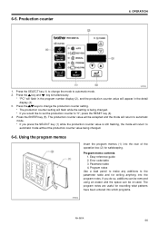
... the production counter value being changed . 6-6. Press the keys to change the mode to the parameter table and for writing anything into which programs. 3054Q RH-981A 44 Press the ENTER key (5). Program notes Use a lead pencil to make any additions to automatic mode. 2. Easy reference guide 2. The program notes are useful... the program memos Insert the program memos (1) into the rear of the operation box (2) for recording what patterns have been entered into the program notes. Error code table 3.
... the production counter value being changed . 6-6. Press the keys to change the mode to the parameter table and for writing anything into which programs. 3054Q RH-981A 44 Press the ENTER key (5). Program notes Use a lead pencil to make any additions to automatic mode. 2. Easy reference guide 2. The program notes are useful... the program memos Insert the program memos (1) into the rear of the operation box (2) for recording what patterns have been entered into the program notes. Error code table 3.
Instruction Manual - Spanish
Page 84
... properly connected. 3. Check that connector P19 on the control circuit board is properly connected. 1. External RAM error Turn off the power. RH-981A 77 Air pressure is OFF. is carried out, check that connector P20 on the control circuit board is ...properly connected. 1. Feed plate left so that connector P2 on the control circuit board is properly connected. is carried out, check that the feed plate home position sensor turns ON. 2. LIST OF ERROR CODES...
... properly connected. 3. Check that connector P19 on the control circuit board is properly connected. 1. External RAM error Turn off the power. RH-981A 77 Air pressure is OFF. is carried out, check that connector P20 on the control circuit board is ...properly connected. 1. Feed plate left so that connector P2 on the control circuit board is properly connected. is carried out, check that the feed plate home position sensor turns ON. 2. LIST OF ERROR CODES...

Instruction Manual - Spanish
Page 85
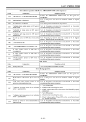
...be ON. circuit board is OFF when it should be Turn the pulley by hand to raise the needle bar to its highest ON. RH-981A 78 Feed plate home position sensor is properly connected. Needle up sensor is not activated within a Turn off the power and check that ... Check that connector P9 on the control circuit board are properly connected. LIST OF ERROR CODES Code E-30 E-32 E-35 E-36 E-37 E-38 E-40 E-42 E-45 E-50 E-51 E-52 Code E-59 Code E-60 E-62 E-66 E-67 E-68 E-70 Errors before operation and after the EMERGENCY STOP switch is OFF. Lower thread trimming OFF ...
...be ON. circuit board is OFF when it should be Turn the pulley by hand to raise the needle bar to its highest ON. RH-981A 78 Feed plate home position sensor is properly connected. Needle up sensor is not activated within a Turn off the power and check that ... Check that connector P9 on the control circuit board are properly connected. LIST OF ERROR CODES Code E-30 E-32 E-35 E-36 E-37 E-38 E-40 E-42 E-45 E-50 E-51 E-52 Code E-59 Code E-60 E-62 E-66 E-67 E-68 E-70 Errors before operation and after the EMERGENCY STOP switch is OFF. Lower thread trimming OFF ...

Instruction Manual - Spanish
Page 86
... P10 on the control circuit board is properly connected. Turn off the power and check that connector P20 on the control specified time. RH-981A 79 Turn off the power. 2. Check that connector P25 on the control circuit board is properly connected. Turn off the power and ... connectors P12 and P13 on the control circuit board is properly connected. LIST OF ERROR CODES Code E-71 E-72 E-75 E-76 E-77 E-80 E-81 E-82 E-89 Code E-90 E-91 E-92 E-93 E-94 E-95 E-96 E-97 E-98 E-99 Errors during test feeding. 1. Needle up sensor is properly connected. Turn off the power...
... P10 on the control circuit board is properly connected. Turn off the power and check that connector P20 on the control specified time. RH-981A 79 Turn off the power. 2. Check that connector P25 on the control circuit board is properly connected. Turn off the power and ... connectors P12 and P13 on the control circuit board is properly connected. LIST OF ERROR CODES Code E-71 E-72 E-75 E-76 E-77 E-80 E-81 E-82 E-89 Code E-90 E-91 E-92 E-93 E-94 E-95 E-96 E-97 E-98 E-99 Errors during test feeding. 1. Needle up sensor is properly connected. Turn off the power...
Instruction Manual - English
Page 7
...9-24.Adjusting the position of limit switch L (-52 specifications 71 9-25.Adjusting the position of the upper thread 66 9-17. LIST OF ERROR CODES 77 13. Adjusting the trimming of limit switch R (-52 specifications 71 10. Adjusting the trimming of the work clamp plate 64 9-15....67 9-20.Auxiliary clamp arm (-02, -52 specifications 68 9-21.Adjusting the cloth feeding speed (-52 specifications 68 9-22. TROUBLESHOOTING 80 RH-981A Adjusting the needle racking width (stitch width 60 9-10.Changing the knife cutting length (Replacing the hammer 61 9-11.Adjusting the contact between ...
...9-24.Adjusting the position of limit switch L (-52 specifications 71 9-25.Adjusting the position of the upper thread 66 9-17. LIST OF ERROR CODES 77 13. Adjusting the trimming of limit switch R (-52 specifications 71 10. Adjusting the trimming of the work clamp plate 64 9-15....67 9-20.Auxiliary clamp arm (-02, -52 specifications 68 9-21.Adjusting the cloth feeding speed (-52 specifications 68 9-22. TROUBLESHOOTING 80 RH-981A Adjusting the needle racking width (stitch width 60 9-10.Changing the knife cutting length (Replacing the hammer 61 9-11.Adjusting the contact between ...
Instruction Manual - English
Page 51
...the program memos Insert the program memos (1) into the rear of the operation box (2) for writing anything into which programs. 3054Q RH-981A 44 Program notes Use a lead pencil to make any additions to automatic mode without the production counter value being changed . 6-6....key (5). Parameter table 4. Production counter 6. The program notes are useful for recording what patterns have been entered into the program notes. Error code table 3. Press the keys to change the mode to change the production counter setting. * The production counter setting will flash while the...
...the program memos Insert the program memos (1) into the rear of the operation box (2) for writing anything into which programs. 3054Q RH-981A 44 Program notes Use a lead pencil to make any additions to automatic mode without the production counter value being changed . 6-6....key (5). Parameter table 4. Production counter 6. The program notes are useful for recording what patterns have been entered into the program notes. Error code table 3. Press the keys to change the mode to change the production counter setting. * The production counter setting will flash while the...

Instruction Manual - English
Page 84
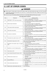
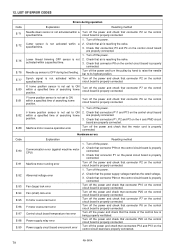
...not support is properly connected. Check that connector P2 on Code E-00 E-02 E-03 E-04 E-05 E-06 E-07 E-09 E-10 E-12 E-15 E-26 E-27 E-28 E-29 Explanation Resetting method EMERGENCY STOP switch was pressed. RH-981A 77 12. Air pressure is tilted back. Feed plate ...home position sensor is turned on the control circuit board is properly connected. is carried out, check that connector P20 on the control circuit board is properly connected. 3. LIST OF ERROR CODES 12. LIST OF ERROR CODES ...
...not support is properly connected. Check that connector P2 on Code E-00 E-02 E-03 E-04 E-05 E-06 E-07 E-09 E-10 E-12 E-15 E-26 E-27 E-28 E-29 Explanation Resetting method EMERGENCY STOP switch was pressed. RH-981A 77 12. Air pressure is tilted back. Feed plate ...home position sensor is turned on the control circuit board is properly connected. is carried out, check that connector P20 on the control circuit board is properly connected. 3. LIST OF ERROR CODES 12. LIST OF ERROR CODES ...
Instruction Manual - English
Page 85
... board is not activated within a specified time. 1. LIST OF ERROR CODES Code E-30 E-32 E-35 E-36 E-37 E-38 E-40 E-42 E-45 E-50 E-51 E-52 Code E-59 Code E-60 E-62 E-66 E-67 E-68 E-70 Errors before operation and after the EMERGENCY STOP switch is properly connected. ... connected. circuit board is properly connected. Turn off the power. 2. circuit board is OFF. RH-981A 78 Lower thread trimming OFF sensor is properly connected. Errors during operation Explanation Resetting method EMERGENCY STOP switch was pressed. 12. Release the EMERGENCY STOP switch and...
... board is not activated within a specified time. 1. LIST OF ERROR CODES Code E-30 E-32 E-35 E-36 E-37 E-38 E-40 E-42 E-45 E-50 E-51 E-52 Code E-59 Code E-60 E-62 E-66 E-67 E-68 E-70 Errors before operation and after the EMERGENCY STOP switch is properly connected. ... connected. circuit board is properly connected. Turn off the power. 2. circuit board is OFF. RH-981A 78 Lower thread trimming OFF sensor is properly connected. Errors during operation Explanation Resetting method EMERGENCY STOP switch was pressed. 12. Release the EMERGENCY STOP switch and...
Instruction Manual - English
Page 86
LIST OF ERROR CODES Code E-71 E-72 E-75 E-76 E-77 E-80 E-81 E-82 E-89 Code E-90 E-91 E-92 E-93 E-94 E-95 E-96 E-97 E-98 E-99 Errors during test feeding. 1. Turn off the power. ...RH-981A 79 circuit board is properly connected. Hardware errors Explanation Resetting method Communication error (against machine motor CPU) Machine motor running error Abnormal voltage error Fan (large) lock error Fan (small) lock error X motor overcurrent error Y motor overcurrent error Control circuit board temperature rise error Power supply relay error Power supply circuit board overcurrent error...
LIST OF ERROR CODES Code E-71 E-72 E-75 E-76 E-77 E-80 E-81 E-82 E-89 Code E-90 E-91 E-92 E-93 E-94 E-95 E-96 E-97 E-98 E-99 Errors during test feeding. 1. Turn off the power. ...RH-981A 79 circuit board is properly connected. Hardware errors Explanation Resetting method Communication error (against machine motor CPU) Machine motor running error Abnormal voltage error Fan (large) lock error Fan (small) lock error X motor overcurrent error Y motor overcurrent error Control circuit board temperature rise error Power supply relay error Power supply circuit board overcurrent error...

