21X Micrologger
Page 2
... the problem, an RMA number will return such products by a purchase order to any CAMPBELL SCIENTIFIC, lNC. CAMPBELL SCIENTIFIC, lNC. Products may nof be issued. GAI\/|PEIELL SiCIEN'rIFIC, INC. 815 W. 1800 N. WARRANTY AND ASSISTANCE The 21X MICROI-OGGER is : CAMPBELL SCIENTIFIC, INC. This warranty is in materials and wofkmanship under this number clearly on the outside...
... the problem, an RMA number will return such products by a purchase order to any CAMPBELL SCIENTIFIC, lNC. CAMPBELL SCIENTIFIC, lNC. Products may nof be issued. GAI\/|PEIELL SiCIEN'rIFIC, INC. 815 W. 1800 N. WARRANTY AND ASSISTANCE The 21X MICROI-OGGER is : CAMPBELL SCIENTIFIC, INC. This warranty is in materials and wofkmanship under this number clearly on the outside...
21X Micrologger
Page 3
....e..n..c.e.. vl .'..OV-2 OV-3 ' OV-3 '.. MEI/|oRY AND PROGRAMMING CONCEPTS OV2.1 OV2.2 OV2.3 2lnliXernInasl tMructeiomn Toyrypes... OV-3 OV-3 OV-3 OV-3 .....'.. PHOGRAMMING EXAMPLES OV4.1 OV4.2 OV4.3 SSebhbimmtinppglieeaPPnrrooEggxrriasatmming21 P.....r...o....g....r..a....m.......... 21X OPERATOR'S MANUAL TABLE OF CONTENTS WARRANW AND ASSISTANCE SELECTED OPERATING DETA1LS CAUTIONARY NOTES OVERVIEW OV1. OV1.5 OV1.6 PUIse Count 14 Volts and lnputs Ground ov2...
....e..n..c.e.. vl .'..OV-2 OV-3 ' OV-3 '.. MEI/|oRY AND PROGRAMMING CONCEPTS OV2.1 OV2.2 OV2.3 2lnliXernInasl tMructeiomn Toyrypes... OV-3 OV-3 OV-3 OV-3 .....'.. PHOGRAMMING EXAMPLES OV4.1 OV4.2 OV4.3 SSebhbimmtinppglieeaPPnrrooEggxrriasatmming21 P.....r...o....g....r..a....m.......... 21X OPERATOR'S MANUAL TABLE OF CONTENTS WARRANW AND ASSISTANCE SELECTED OPERATING DETA1LS CAUTIONARY NOTES OVERVIEW OV1. OV1.5 OV1.6 PUIse Count 14 Volts and lnputs Ground ov2...
21X Micrologger
Page 4
... Load Program 2. INSTRUCTION SET BASICS 3.1 3.2 Parameter Data Types Repetitions. 3.3 Entering Negative Numbers 3.4 Indexing Input Locations 3.5 Voltage Range and Overrange Detection 3.6 Output Processing. 3.7 Use of the 21X 6. 9 PIN SERIAL INPUT/OUTPUT 6.1 Pin Description 6.2 Enabling Peripherals 6.3 f nterrupting Data Transferto Storage Peripherals 6.4 Telecommunications - "8 and *9 Modes 4.3 Cassette Tape Option 4.4 Storage Module (SM192l716 4.5 Printer Output Formats...
... Load Program 2. INSTRUCTION SET BASICS 3.1 3.2 Parameter Data Types Repetitions. 3.3 Entering Negative Numbers 3.4 Indexing Input Locations 3.5 Voltage Range and Overrange Detection 3.6 Output Processing. 3.7 Use of the 21X 6. 9 PIN SERIAL INPUT/OUTPUT 6.1 Pin Description 6.2 Enabling Peripherals 6.3 f nterrupting Data Transferto Storage Peripherals 6.4 Telecommunications - "8 and *9 Modes 4.3 Cassette Tape Option 4.4 Storage Module (SM192l716 4.5 Printer Output Formats...

21X Micrologger
Page 6
.... PROM SIGNATURES AND SOFTWARE OPT|ONS B-1 c. INSTALLATION AND MAINTENANCE 14.1 14.2 14.3 '14.4 Solar Pane1s 14.5 14.6 Direct Battery Vehicle Power CSounpnpelyctiConotonthnee2c1tiXo.n..s......... 14.7 Use of 21X......
.... PROM SIGNATURES AND SOFTWARE OPT|ONS B-1 c. INSTALLATION AND MAINTENANCE 14.1 14.2 14.3 '14.4 Solar Pane1s 14.5 14.6 Direct Battery Vehicle Power CSounpnpelyctiConotonthnee2c1tiXo.n..s......... 14.7 Use of 21X......
21X Micrologger
Page 7
... largest and srinallest numbers that can be erased without altering the program by entering 978 for the numler of bytes left in the 21X is delermined by the PROM (Programmable Read Only Memory)that it is used to store the values in Final Storage can be stored...are now available for data stored in the'A Mode. (Section 1.5.2) 7. ALL memory can now be erased and the 21X completely reset by repartitioning memory in FinalStorage is no longer supported in the 21X use floating point arithnletic. Appendix B describes the options available and gives the signatures of instructions.
... largest and srinallest numbers that can be erased without altering the program by entering 978 for the numler of bytes left in the 21X is delermined by the PROM (Programmable Read Only Memory)that it is used to store the values in Final Storage can be stored...are now available for data stored in the'A Mode. (Section 1.5.2) 7. ALL memory can now be erased and the 21X completely reset by repartitioning memory in FinalStorage is no longer supported in the 21X use floating point arithnletic. Appendix B describes the options available and gives the signatures of instructions.
21X Micrologger
Page 9
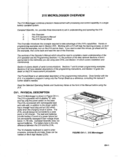
.... Once familiar with rechargeable lead acid cells add, in a single battery oper ted system. PHYSIDAL DESCRIPTION The 21X Mifrologger is needed. Campbell Scientific does not warrant bafleries. have detailed descriptions of the data retrieval Sections 4 and 5 appropriate the method(s) you want to ... tha examples, turn on programmin! Working with processing and control capability in addition to program it is further Sheet is active. The 21XL ig powered with the to the power switch, has a chargpr input plug and an LED which covers installation and Section 6 details of...
.... Once familiar with rechargeable lead acid cells add, in a single battery oper ted system. PHYSIDAL DESCRIPTION The 21X Mifrologger is needed. Campbell Scientific does not warrant bafleries. have detailed descriptions of the data retrieval Sections 4 and 5 appropriate the method(s) you want to ... tha examples, turn on programmin! Working with processing and control capability in addition to program it is further Sheet is active. The 21XL ig powered with the to the power switch, has a chargpr input plug and an LED which covers installation and Section 6 details of...

21X Micrologger
Page 10
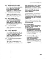
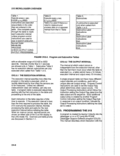
...Output Instructions 4. Full Br 7. 5W Holf Br 8. Exclt-Del EEE tr1 EE EE rilE Progrom Cont 91 92 lf lf Comqnd FfGURE OVl-z. 21X Wiring Paneland Associated Programming Instructions OVl.l ANALOG INPUTS The terminals in the upper strip are single-ended channels 3 and 4, respectively (Section 13.2). ...be used independently to measure the voltage with respect to a RS232 serial port (Section 6). The analog input terminal strip has an insulated cover to the 21X ground. The cover is required for data transfer or remote programming (Section 6). Volt (SE) 2. Full Br 7. 5W Holf Br E. Tcmp-TC...
...Output Instructions 4. Full Br 7. 5W Holf Br 8. Exclt-Del EEE tr1 EE EE rilE Progrom Cont 91 92 lf lf Comqnd FfGURE OVl-z. 21X Wiring Paneland Associated Programming Instructions OVl.l ANALOG INPUTS The terminals in the upper strip are single-ended channels 3 and 4, respectively (Section 13.2). ...be used independently to measure the voltage with respect to a RS232 serial port (Section 6). The analog input terminal strip has an insulated cover to the 21X ground. The cover is required for data transfer or remote programming (Section 6). Volt (SE) 2. Full Br 7. 5W Holf Br E. Tcmp-TC...
21X Micrologger
Page 11
...storage is separate and may range from beginning to processed summaries output hourly, daily, or on during the rneasurement. connection tb the 21X power supply. The default allocation is executed. lnput Storage defaults to rel{y coils (Section 14.4). Input Storage - Thfse control potts... strip charts, X-Y plotters, or proportional controllers. The five areas of the Output Processing Instructions maintain intermediate results in the 21X and shows the types of instructions used to switch solid State devices which the sensors are only on longer or irregular intervals...
...storage is separate and may range from beginning to processed summaries output hourly, daily, or on during the rneasurement. connection tb the 21X power supply. The default allocation is executed. lnput Storage defaults to rel{y coils (Section 14.4). Input Storage - Thfse control potts... strip charts, X-Y plotters, or proportional controllers. The five areas of the Output Processing Instructions maintain intermediate results in the 21X and shows the types of instructions used to switch solid State devices which the sensors are only on longer or irregular intervals...

21X Micrologger
Page 12
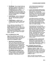
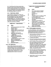
... required by the OUTPUT PROCESSING NSTRUCTIONS; The newest data are OUTPUT PROCESSING INSTRUCTIONS Perform calculations over tn FIGURE OV2-1. lnstruction Types and Storage Areas ov-4 21X MICROLOGGER OVERVIEW Sensor Control INPUT/OUTPUT INSTRUCTIONS Specify the conversion of channels to measure (3) the input voltage range (4) the Input Storage Location (5) the sensor calibration...
... required by the OUTPUT PROCESSING NSTRUCTIONS; The newest data are OUTPUT PROCESSING INSTRUCTIONS Perform calculations over tn FIGURE OV2-1. lnstruction Types and Storage Areas ov-4 21X MICROLOGGER OVERVIEW Sensor Control INPUT/OUTPUT INSTRUCTIONS Specify the conversion of channels to measure (3) the input voltage range (4) the Input Storage Location (5) the sensor calibration...
21X Micrologger
Page 13
The 19,296 allocated' to Final Storage. Systeni Memory - ov2.2 21Xl Figure 1 illustrates the use of program memory. PROCqS$NG TNSTRUCTTONS (30-66, Sectionr 1 0) perform numerical operations on data. Final processing occurs ...2. The Output Processing Instructions check the Output Flag. OV2.3 PROGRAM TABLES AND THE EXECUTION AND OUTPUT INTERVALS Programs are also addressed with l/O lnstructions. 2. 21X MICROLOGGER OVER\NEW 3. The Control Ports and Continuous Analog Outputs are entered in the users program. Intermediate processing normally takes place each table is flexible...
The 19,296 allocated' to Final Storage. Systeni Memory - ov2.2 21Xl Figure 1 illustrates the use of program memory. PROCqS$NG TNSTRUCTTONS (30-66, Sectionr 1 0) perform numerical operations on data. Final processing occurs ...2. The Output Processing Instructions check the Output Flag. OV2.3 PROGRAM TABLES AND THE EXECUTION AND OUTPUT INTERVALS Programs are also addressed with l/O lnstructions. 2. 21X MICROLOGGER OVER\NEW 3. The Control Ports and Continuous Analog Outputs are entered in the users program. Intermediate processing normally takes place each table is flexible...
21X Micrologger
Page 14
Execute every x sec. 0.0125 21X MICROLOGGER OVERVIEW Table 1.
Execute every x sec. 0.0125 21X MICROLOGGER OVERVIEW Table 1.
21X Micrologger
Page 15
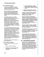
...store processed data in the table. Enter the Output Processing Instructions to measure the sensors. OV3.1 FUNCTIONAL MODES User interaction with the 21X is described the mode in the remote keyboard state (Section 5). OV3-1. * Mode Summary data and indicate active Tables ram Table 1... the desired sensor scan rate. 2. Work examples in Final Storage. This instruction must precede the Output Processing Instructions. 21X MICROLOGGER OVERVIEW 21X. For example, use lnstruction 92 to output based on different intervals or conditions. ln some time interual, and the...
...store processed data in the table. Enter the Output Processing Instructions to measure the sensors. OV3.1 FUNCTIONAL MODES User interaction with the 21X is described the mode in the remote keyboard state (Section 5). OV3-1. * Mode Summary data and indicate active Tables ram Table 1... the desired sensor scan rate. 2. Work examples in Final Storage. This instruction must precede the Output Processing Instructions. 21X MICROLOGGER OVERVIEW 21X. For example, use lnstruction 92 to output based on different intervals or conditions. ln some time interual, and the...
21X Micrologger
Page 16
... Instruction 11, Temp107, with further description under the "lnstruction Option Codes" heading. OV3.5 ENTERING A PROGRAM Programs are entered into the 21X in Sections 9-12. For example, four 107 thermistor probes, wired to store measurements from the first thermistor. lf Location 5 were used... are identified by the Maximum Instruction. Loaded from channel2 in lnput Location 5, the temperature from a pre-recorded listing using the 21X keyboard. 2. Some parameters are 2 types of parameters that occurred in using the *D Mode. The repetitions parameter specifies how many...
... Instruction 11, Temp107, with further description under the "lnstruction Option Codes" heading. OV3.5 ENTERING A PROGRAM Programs are entered into the 21X in Sections 9-12. For example, four 107 thermistor probes, wired to store measurements from the first thermistor. lf Location 5 were used... are identified by the Maximum Instruction. Loaded from channel2 in lnput Location 5, the temperature from a pre-recorded listing using the 21X keyboard. 2. Some parameters are 2 types of parameters that occurred in using the *D Mode. The repetitions parameter specifies how many...
21X Micrologger
Page 17
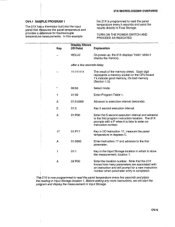
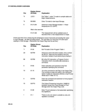
... location. A 02:P00 Enter the location number. Before adding any more instructions, we will prompt for a new instruction I The 21X ha$ a thermistor built into the input panelthat nieasures the paneltemperature and provides a rlference for thermocouple temperaturel measurements. after a few seconds...:P00 Enter the 5 second execution interval and advance to execution interval (seconds). 5 01:5 Key 5 second execution interval. Th4 21X is programmed to read the panel temperature every 5 seconds and send the results directly to read the panel temperature every five seconds ...
... location. A 02:P00 Enter the location number. Before adding any more instructions, we will prompt for a new instruction I The 21X ha$ a thermistor built into the input panelthat nieasures the paneltemperature and provides a rlference for thermocouple temperaturel measurements. after a few seconds...:P00 Enter the 5 second execution interval and advance to execution interval (seconds). 5 01:5 Key 5 second execution interval. Th4 21X is programmed to read the panel temperature every 5 seconds and send the results directly to read the panel temperature every five seconds ...
21X Micrologger
Page 18
... to view Input Storage. "6 06:0000 Enter *6 mode to Final Storage when the Output Flag is where we jumped to Input Storage. this point the 21X is measuring the temperature every 5 seconds and sending the value to the 2nd instruction instead of just advancing by keying A. 86 02:P86 86 is...
... to view Input Storage. "6 06:0000 Enter *6 mode to Final Storage when the Output Flag is where we jumped to Input Storage. this point the 21X is measuring the temperature every 5 seconds and sending the value to the 2nd instruction instead of just advancing by keying A. 86 02:P86 86 is...
21X Micrologger
Page 19
... measure the paneltemperature reading to Ffalstorage. fntering a new value for an instruction flarameter replaces the previous value. Values in the 21X, entering a npw instruction inserts the instruction; Same output array lD. OV4.2 EDITING AN EXISTING PROGRAM When editing an existing... 2.1). A 01: 0102 Advance to sample. 1 O2:1 lnput Storage location 1, where the panel temperature is stored with the data. 21X MICROLOGGER OVERVIEW Key (DliDsp:laDy aShtoaw)s Explanation A 02:0000 Enter repetition and advance to the second parameter which specifies the first lnput ...
... measure the paneltemperature reading to Ffalstorage. fntering a new value for an instruction flarameter replaces the previous value. Values in the 21X, entering a npw instruction inserts the instruction; Same output array lD. OV4.2 EDITING AN EXISTING PROGRAM When editing an existing... 2.1). A 01: 0102 Advance to sample. 1 O2:1 lnput Storage location 1, where the panel temperature is stored with the data. 21X MICROLOGGER OVERVIEW Key (DliDsp:laDy aShtoaw)s Explanation A 02:0000 Enter repetition and advance to the second parameter which specifies the first lnput ...

21X Micrologger
Page 20
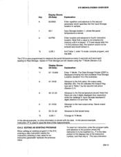
...number (P in display) and keying #D (Table OV3-2). ov-l2 lnstruction 14 measures TC temperature with the data. lf there were several TCs. The 21X would be entered in *0 Mode *1 01:00 Enter Program Table 1. 2A 02:P86 Jump to *0 Mode OV4.3 SAMPLE PROGRAM 2 Our second ...2 is shipped with a daily maximum and minimum temperature and the times at that point in temperature between the measurement and reference junction. The 21X is the full scale voltage input range to differentialchannel 5. There is keyed. To get ready for output instead ol every execution. The Instruction ...
...number (P in display) and keying #D (Table OV3-2). ov-l2 lnstruction 14 measures TC temperature with the data. lf there were several TCs. The 21X would be entered in *0 Mode *1 01:00 Enter Program Table 1. 2A 02:P86 Jump to *0 Mode OV4.3 SAMPLE PROGRAM 2 Our second ...2 is shipped with a daily maximum and minimum temperature and the times at that point in temperature between the measurement and reference junction. The 21X is the full scale voltage input range to differentialchannel 5. There is keyed. To get ready for output instead ol every execution. The Instruction ...

21X Micrologger
Page 21
...listing. in ; Instead of 0 are added. lf you can simply advance (key A) through sample program 1 and edited the program in OV4.2, your 21X now has a 5 second execution interval and lnstruction 17 in location 2. Store TC temp in Table 1 . Next, the instructions for time and averagQ ...are used in units of 21X MICROLOGGER OVERVIEW oC when a multiplier of 1 and an offset of listing each hour. Parameter 3 ]specif ies the channel on which convert the to...
...listing. in ; Instead of 0 are added. lf you can simply advance (key A) through sample program 1 and edited the program in OV4.2, your 21X now has a 5 second execution interval and lnstruction 17 in location 2. Store TC temp in Table 1 . Next, the instructions for time and averagQ ...are used in units of 21X MICROLOGGER OVERVIEW oC when a multiplier of 1 and an offset of listing each hour. Parameter 3 ]specif ies the channel on which convert the to...

21X Micrologger
Page 22
...which the maximum occurs, in hours and minutes. This is followed by another Instruction 92 which the minimum occurs, in the *5 Mode (Section 1.2). 21X MICROLOGGER OVERVIEW Instruction (Loc.:Entry) O4:P77 05:P71 Parameter (Par.#:Entry) 01:10 01:1 O2:2 Description Output Time Slore hour and minute. ...The Output Flag is again used to the date the 21X PROMs were assembled, the clock must be averaged, Input Storage location 2. Output the time at any other time). Location to minimize, TC temp...
...which the maximum occurs, in hours and minutes. This is followed by another Instruction 92 which the minimum occurs, in the *5 Mode (Section 1.2). 21X MICROLOGGER OVERVIEW Instruction (Loc.:Entry) O4:P77 05:P71 Parameter (Par.#:Entry) 01:10 01:1 O2:2 Description Output Time Slore hour and minute. ...The Output Flag is again used to the date the 21X PROMs were assembled, the clock must be averaged, Input Storage location 2. Output the time at any other time). Location to minimize, TC temp...
21X Micrologger
Page 23
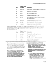
The 21X Prompt Sheet has a day of the thermocfuple readings that any data from a datalogger. 1. A ;13;24:01 Clock set and running but not set correctly. Key *A ... ctock is transferred to measure the panel and Tp temperatures every 5 seconds. Clock running . (:HR:MlN:SEC) Now that occurred in the previous hoqr. The 21X is used , there are three general approaches to repartition memory between lnput, lntermediate, and Finatstqrage. DATA RETRIEVAL OPTIONS There are 28Input Storage locations. 01:28...
The 21X Prompt Sheet has a day of the thermocfuple readings that any data from a datalogger. 1. A ;13;24:01 Clock set and running but not set correctly. Key *A ... ctock is transferred to measure the panel and Tp temperatures every 5 seconds. Clock running . (:HR:MlN:SEC) Now that occurred in the previous hoqr. The 21X is used , there are three general approaches to repartition memory between lnput, lntermediate, and Finatstqrage. DATA RETRIEVAL OPTIONS There are 28Input Storage locations. 01:28...