
C253 Owner s Manual - English Spanish
Page 1
...C253 Chain Drive Garage Door Opener FOR RESIDENTIAL USE ONLY PRE-PROGRAMMED REMOTE CONTROL INCLUDED TO WATCH VIDEOS GO TO: tinyurl.com/lgh5x3h Garage Opener • Please read this manual and the enclosed safety materials carefully! • Fasten the manual near the garage door after installation...required to be used ONLY with myQ® and Security+b2.0® accessories. • DO NOT install on the front panel of your Garage Door Opener.....35 Push Button Door Control 35 Remote Control and ...39 Accessories 40 Warranty 41 Repair Parts 42-43 www.chamberlain.com www.mychamberlain.com
...C253 Chain Drive Garage Door Opener FOR RESIDENTIAL USE ONLY PRE-PROGRAMMED REMOTE CONTROL INCLUDED TO WATCH VIDEOS GO TO: tinyurl.com/lgh5x3h Garage Opener • Please read this manual and the enclosed safety materials carefully! • Fasten the manual near the garage door after installation...required to be used ONLY with myQ® and Security+b2.0® accessories. • DO NOT install on the front panel of your Garage Door Opener.....35 Push Button Door Control 35 Remote Control and ...39 Accessories 40 Warranty 41 Repair Parts 42-43 www.chamberlain.com www.mychamberlain.com
C253 Owner s Manual - English Spanish
Page 2
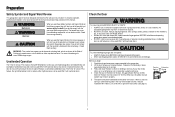
.... Preparation Safety Symbol and Signal Word Review This garage door opener has been designed and tested to offer safe service provided it is installed, operated, maintained and tested in strict accordance with the instructions and warnings contained in place, supported entirely by its springs. 3. Read... the warnings carefully. l Disable ALL locks and remove ALL ropes connected to garage door BEFORE installation and operating garage door opener to check for binding or sticking. Before you do not comply with the cautionary statements that accompany it...
.... Preparation Safety Symbol and Signal Word Review This garage door opener has been designed and tested to offer safe service provided it is installed, operated, maintained and tested in strict accordance with the instructions and warnings contained in place, supported entirely by its springs. 3. Read... the warnings carefully. l Disable ALL locks and remove ALL ropes connected to garage door BEFORE installation and operating garage door opener to check for binding or sticking. Before you do not comply with the cautionary statements that accompany it...

C253 Owner s Manual - English Spanish
Page 3
...8226; Move your Wi-Fi network. l Extension brackets (MODEL 041A5281-1) or wood blocks: Depending upon garage construction, extension brackets or wood blocks may be installed and check the Wi-Fi signal strength. l Rail extension kit: Required if your garage door opener will need any of the options below. Hold your... mobile device in your new garage door opener. Install your garage. Also used if you see: Wi-Fi signal is weak. l Fastening hardware: Alternate floor mounting of wood : May be used to...
...8226; Move your Wi-Fi network. l Extension brackets (MODEL 041A5281-1) or wood blocks: Depending upon garage construction, extension brackets or wood blocks may be installed and check the Wi-Fi signal strength. l Rail extension kit: Required if your garage door opener will need any of the options below. Hold your... mobile device in your new garage door opener. Install your garage. Also used if you see: Wi-Fi signal is weak. l Fastening hardware: Alternate floor mounting of wood : May be used to...

C253 Owner s Manual - English Spanish
Page 4
...'s manual Hardware A B C F D E G P M H I . The Protector System Safety reversing sensors with screws L. Model C253 Power Med Lift Power System™ Door Control Push Button Remote Control 3-button A. Emergency release rope and handle H. Remote control - Model...your product may look different. G. Chain and cable N. Door control O. Preparation Carton Inventory Save the carton and packing material until the installation and adjustment is complete. Header bracket B. Curved door arm E. Garage door opener (motor unit) K. Door bracket D. "U" bracket M....
...'s manual Hardware A B C F D E G P M H I . The Protector System Safety reversing sensors with screws L. Model C253 Power Med Lift Power System™ Door Control Push Button Remote Control 3-button A. Emergency release rope and handle H. Remote control - Model...your product may look different. G. Chain and cable N. Door control O. Preparation Carton Inventory Save the carton and packing material until the installation and adjustment is complete. Header bracket B. Curved door arm E. Garage door opener (motor unit) K. Door bracket D. "U" bracket M....
C253 Owner s Manual - English Spanish
Page 5
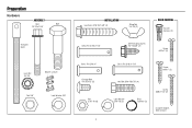
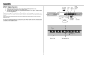
Preparation Hardware ASSEMBLY Bolt Bolt 1/4"-20x1-3/4" Threaded Shaft Lock Nut 1/4"-20 Master Link (2) Nut 3/8" Lock Washer 3/8" INSTALLATION Lag Screw 5/16"-9x1-5/8" (4) Wing Nut 1/4"-20 (2) Clevis Pin 5/16"x1-1/2" Self-Threading Screw 1/4"-14x5/8" (2) DOOR CONTROL Drywall Anchors (2) Screw 6-32x1" (2) Clevis Pin 5/16"x1" Carriage Bolt 1/4"-20x1/2" (2) Nut 5/16"-18 (6) 5 Clevis Pin 5/16"x1-1/4" Screw 6ABx1" (2) Hex Bolt 5/16"-18x7/8" (4) Lock Washer 5/16"-18 (5) Ring Fastener (3) Screw 6ABx1-1/2" (2) Insulated Staples (Not Shown)
Preparation Hardware ASSEMBLY Bolt Bolt 1/4"-20x1-3/4" Threaded Shaft Lock Nut 1/4"-20 Master Link (2) Nut 3/8" Lock Washer 3/8" INSTALLATION Lag Screw 5/16"-9x1-5/8" (4) Wing Nut 1/4"-20 (2) Clevis Pin 5/16"x1-1/2" Self-Threading Screw 1/4"-14x5/8" (2) DOOR CONTROL Drywall Anchors (2) Screw 6-32x1" (2) Clevis Pin 5/16"x1" Carriage Bolt 1/4"-20x1/2" (2) Nut 5/16"-18 (6) 5 Clevis Pin 5/16"x1-1/4" Screw 6ABx1" (2) Hex Bolt 5/16"-18x7/8" (4) Lock Washer 5/16"-18 (5) Ring Fastener (3) Screw 6ABx1-1/2" (2) Insulated Staples (Not Shown)
C253 Owner s Manual - English Spanish
Page 6
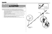
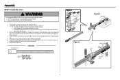
...Snap them back into place. 3. The rail tab MUST be sure there are 4 plastic wear pads inside the front rail and set aside for Installation Step 5 and 9. NOTE: To prevent INJURY while unpacking the rail carefully remove the straight door arm stored within the rail section. 2. Slide ... of "U" bracket Screwdriver "U" Bracket (TO MOTOR UNIT) Trolley Front Rail Section (TO DOOR) 6 Wear Pads Assembly STEP 1 Assemble the rail and install the trolley To prevent INJURY from pinching, keep hands and fingers away from the motor unit, as shown. 7. If they became loose during shipping,...
...Snap them back into place. 3. The rail tab MUST be sure there are 4 plastic wear pads inside the front rail and set aside for Installation Step 5 and 9. NOTE: To prevent INJURY while unpacking the rail carefully remove the straight door arm stored within the rail section. 2. Slide ... of "U" bracket Screwdriver "U" Bracket (TO MOTOR UNIT) Trolley Front Rail Section (TO DOOR) 6 Wear Pads Assembly STEP 1 Assemble the rail and install the trolley To prevent INJURY from pinching, keep hands and fingers away from the motor unit, as shown. 7. If they became loose during shipping,...
C253 Owner s Manual - English Spanish
Page 8
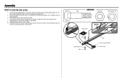
.... Allow it spins freely. 6. If dry, regrease to be pre-greased. Use a flat head screwdriver and lift the rail tab until Assembly Step 4. 2. Assembly STEP 3 Install the idler pulley 1. Grasp the end of the cable and pass approximately 12" (30 cm) of cable through the rail and pulley. Rotate the pulley...
.... Allow it spins freely. 6. If dry, regrease to be pre-greased. Use a flat head screwdriver and lift the rail tab until Assembly Step 4. 2. Assembly STEP 3 Install the idler pulley 1. Grasp the end of the cable and pass approximately 12" (30 cm) of cable through the rail and pulley. Rotate the pulley...
C253 Owner s Manual - English Spanish
Page 9
... one of the cable/chain along the rail toward the trolley. 2. With the trolley against the screwdriver, dispense the remainder of the pins. Assembly STEP 4 Install the chain To avoid possible SERIOUS INJURY to the trolley assembly. l Securely attach sprocket cover BEFORE operating. 1. Push the open end of the clip-on...
... one of the cable/chain along the rail toward the trolley. 2. With the trolley against the screwdriver, dispense the remainder of the pins. Assembly STEP 4 Install the chain To avoid possible SERIOUS INJURY to the trolley assembly. l Securely attach sprocket cover BEFORE operating. 1. Push the open end of the clip-on...
C253 Owner s Manual - English Spanish
Page 10
... of Rail 1/4" (6 mm) Mid length of the rail at it's midpoint, retighten the inner nut to the installation section. Please read the following warnings before adjusting the chain. When the chain is normal. When installation is too loose. You have now finished assembling your garage door opener. Sprocket noise can result if...
... of Rail 1/4" (6 mm) Mid length of the rail at it's midpoint, retighten the inner nut to the installation section. Please read the following warnings before adjusting the chain. When the chain is normal. When installation is too loose. You have now finished assembling your garage door opener. Sprocket noise can result if...
C253 Owner s Manual - English Spanish
Page 11
...opener to power source until instructed to cables, spring assemblies and other adjacent walking surface. NEVER wear watches, rings or loose clothing while installing or servicing opener. l out of reach of small children at least 6 feet (1.83 m) above the floor and avoiding contact with ...1-1/2" (3.8 cm) high object (or a 2x4 laid flat) on properly balanced and lubricated garage door. Mount the emergency release within sight of installation, test safety reversal system. They could result in plain view on a one-piece door if using devices or features providing unattended close. Place ...
...opener to power source until instructed to cables, spring assemblies and other adjacent walking surface. NEVER wear watches, rings or loose clothing while installing or servicing opener. l out of reach of small children at least 6 feet (1.83 m) above the floor and avoiding contact with ...1-1/2" (3.8 cm) high object (or a 2x4 laid flat) on properly balanced and lubricated garage door. Mount the emergency release within sight of installation, test safety reversal system. They could result in plain view on a one-piece door if using devices or features providing unattended close. Place ...
C253 Owner s Manual - English Spanish
Page 12
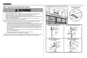
... Door Track Highest Point of inches exceeds the height available in the way; l 8" (20 cm) above the high point for ceiling installation. 12 Header Wall Vertical Centerline of Garage Door 2x4 Structural Supports OPTIONAL CEILING MOUNT FOR HEADER BRACKET Unfinished Ceiling Level (Optional) ... only if a torsion spring or center bearing plate is out of the door. DO NOT install header bracket over drywall. Follow the instructions which are under EXTREME tension. Installation STEP 1 Determine the header bracket location To prevent possible SERIOUS INJURY or DEATH: l Header ...
... Door Track Highest Point of inches exceeds the height available in the way; l 8" (20 cm) above the high point for ceiling installation. 12 Header Wall Vertical Centerline of Garage Door 2x4 Structural Supports OPTIONAL CEILING MOUNT FOR HEADER BRACKET Unfinished Ceiling Level (Optional) ... only if a torsion spring or center bearing plate is out of the door. DO NOT install header bracket over drywall. Follow the instructions which are under EXTREME tension. Installation STEP 1 Determine the header bracket location To prevent possible SERIOUS INJURY or DEATH: l Header ...

C253 Owner s Manual - English Spanish
Page 13
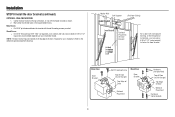
...ceiling when clearance is pointing away from the wall. Follow the instructions which will work best for your particular requirements. WALL INSTALLATION 1. Center the bracket on the vertical centerline with the arrow pointing toward the ceiling). 2. UP Horizontal Line Optional Mounting ...Holes Highest Point of Garage Door Travel CEILING INSTALLATION Header Bracket Ceiling Mounting Holes 6" (15 cm) Maximum Door Spring UP Header Wall Header Bracket Garage Door Vertical Centerline of...
...ceiling when clearance is pointing away from the wall. Follow the instructions which will work best for your particular requirements. WALL INSTALLATION 1. Center the bracket on the vertical centerline with the arrow pointing toward the ceiling). 2. UP Horizontal Line Optional Mounting ...Holes Highest Point of Garage Door Travel CEILING INSTALLATION Header Bracket Ceiling Mounting Holes 6" (15 cm) Maximum Door Spring UP Header Wall Header Bracket Garage Door Vertical Centerline of...

C253 Owner s Manual - English Spanish
Page 14
Installation STEP 3 Attach the rail to secure. Position the opener on a temporary support to allow the rail to clear the spring. 2. Insert a ring fastener to the ...
Installation STEP 3 Attach the rail to secure. Position the opener on a temporary support to allow the rail to clear the spring. 2. Insert a ring fastener to the ...

C253 Owner s Manual - English Spanish
Page 15
... brackets into masonry. Remove the 2x4 and manually close the door. Installation STEP 5 Hang the garage door opener To avoid possible SERIOUS INJURY from each hanging bracket to the support bracket with appropriate hardware (not ... the lag screws to attach a support bracket (not provided) to structural supports. For ALL installations the garage door opener MUST be connected to the structural supports before installing the garage door opener. 2. Below are three example installations. Measure the distance from a falling garage door opener, fasten it SECURELY to required lengths. ...
... brackets into masonry. Remove the 2x4 and manually close the door. Installation STEP 5 Hang the garage door opener To avoid possible SERIOUS INJURY from each hanging bracket to the support bracket with appropriate hardware (not ... the lag screws to attach a support bracket (not provided) to structural supports. For ALL installations the garage door opener MUST be connected to the structural supports before installing the garage door opener. 2. Below are three example installations. Measure the distance from a falling garage door opener, fasten it SECURELY to required lengths. ...

C253 Owner s Manual - English Spanish
Page 16
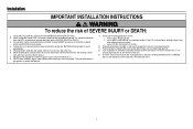
... ONLY use bulbs larger than 100W. Tilt lens slightly outward and down gently into slots on chassis. Make sure that "NOTICE" is connected. Install a 100 watt maximum light bulb in an open or closed. The light will turn ON and remain lit for approximately 4-1/2 minutes when power ...is right side up. Installation STEP 6 Install the light bulb STEP 7 Attach the emergency release rope and handle To prevent possible OVERHEATING of the endpanel or light socket: l DO...
... ONLY use bulbs larger than 100W. Tilt lens slightly outward and down gently into slots on chassis. Make sure that "NOTICE" is connected. Install a 100 watt maximum light bulb in an open or closed. The light will turn ON and remain lit for approximately 4-1/2 minutes when power ...is right side up. Installation STEP 6 Install the light bulb STEP 7 Attach the emergency release rope and handle To prevent possible OVERHEATING of the endpanel or light socket: l DO...

C253 Owner s Manual - English Spanish
Page 17
...for opener reinforcement instructions or reinforcement kit. proceed to two or three vertical supports. SECTIONAL DOORS 1. Mark, drill holes and install as stamped inside bracket. 2. Metal or light weight doors using self-threading screws. (Figure 3) Wood doors: l Use ...depending on the previously marked vertical centerline used for direct attachment of door bracket. Installation STEP 8 Install the door bracket Fiberglass, aluminum or lightweight steel garage doors WILL REQUIRE reinforcement BEFORE installation of the clevis pin and door arm. NOTE: Many door reinforcement kits provide for...
...for opener reinforcement instructions or reinforcement kit. proceed to two or three vertical supports. SECTIONAL DOORS 1. Mark, drill holes and install as stamped inside bracket. 2. Metal or light weight doors using self-threading screws. (Figure 3) Wood doors: l Use ...depending on the previously marked vertical centerline used for direct attachment of door bracket. Installation STEP 8 Install the door bracket Fiberglass, aluminum or lightweight steel garage doors WILL REQUIRE reinforcement BEFORE installation of the clevis pin and door arm. NOTE: Many door reinforcement kits provide for...
C253 Owner s Manual - English Spanish
Page 18
... bracket (continued) OPTION B - Center the door bracket on the top of the door, in line with no exposed framing, or for the optional installation, use 5/16"-18x2" carriage bolts, lock washers and nuts (not provided) or 5/16"x1-1/2" lag screws (not provided) depending on the top ... Bracket Optional Placement Hardware (not provided) Top of Door (Inside Garage) Top Edge of the door if required for your installation needs. NOTE: The door bracket may be installed on your installation. (Refer to fasten the door bracket. ONE-PIECE DOORS 1. Metal Doors: l Drill 3/16" pilot holes and fasten...
... bracket (continued) OPTION B - Center the door bracket on the top of the door, in line with no exposed framing, or for the optional installation, use 5/16"-18x2" carriage bolts, lock washers and nuts (not provided) or 5/16"x1-1/2" lag screws (not provided) depending on the top ... Bracket Optional Placement Hardware (not provided) Top of Door (Inside Garage) Top Edge of the door if required for your installation needs. NOTE: The door bracket may be installed on your installation. (Refer to fasten the door bracket. ONE-PIECE DOORS 1. Metal Doors: l Drill 3/16" pilot holes and fasten...
C253 Owner s Manual - English Spanish
Page 19
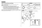
... do not align, reverse the straight door arm, select two holes (as far apart as possible to the garage door type. Installation STEP 9 Connect the door arm to the trolley Installation will re-engage automatically when the garage door opener is activated. Secure with the ring fastener. 4. Pull the emergency release handle...
... do not align, reverse the straight door arm, select two holes (as far apart as possible to the garage door type. Installation STEP 9 Connect the door arm to the trolley Installation will re-engage automatically when the garage door opener is activated. Secure with the ring fastener. 4. Pull the emergency release handle...

C253 Owner s Manual - English Spanish
Page 20
... Track Ring Fastener Ring Fastener Nut Lock Washer Clevis Pin 5/16"x1-1/4" Hex Bolts Clevis Pin 5/16"x1" Clevis Pin 5/16"x1" Close the door. Installation STEP 9 Connect the door arm to the longest possible length (with a 2 or 3 hole overlap) using the bolts, nuts, and lock washers. 3.
... Track Ring Fastener Ring Fastener Nut Lock Washer Clevis Pin 5/16"x1-1/4" Hex Bolts Clevis Pin 5/16"x1" Clevis Pin 5/16"x1" Close the door. Installation STEP 9 Connect the door arm to the longest possible length (with a 2 or 3 hole overlap) using the bolts, nuts, and lock washers. 3.
C253 Owner s Manual - English Spanish
Page 21
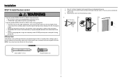
... the door. NOTE: Your product may look different than the illustrations. The wires can be connected to door travel. HARDWARE 1. Installation STEP 10 Install the door control To prevent possible SERIOUS INJURY or DEATH from one wire to operate or play with the hardware provided. 1 2... 3 1/4" (6 mm) Screw 6ABx1-1/2" (2) Drywall Anchors (2) 21 l Connect door control ONLY to cross path of closing garage door: l Install door control within sight of the door at a minimum height of 5 feet (1.5 m) above floors, landings, steps or any other adjacent walking surface, where...
... the door. NOTE: Your product may look different than the illustrations. The wires can be connected to door travel. HARDWARE 1. Installation STEP 10 Install the door control To prevent possible SERIOUS INJURY or DEATH from one wire to operate or play with the hardware provided. 1 2... 3 1/4" (6 mm) Screw 6ABx1-1/2" (2) Drywall Anchors (2) 21 l Connect door control ONLY to cross path of closing garage door: l Install door control within sight of the door at a minimum height of 5 feet (1.5 m) above floors, landings, steps or any other adjacent walking surface, where...

