
PD512 Owner Manual
Page 1
... be used ONLY with Security+ 2.0® accessories. ■ DO NOT install on the front panel of Purchase: www.chamberlain.com The Chamberlain Group, Inc. 845 Larch Avenue Elmhurst, Illinois 60126-1196 1/2 hp Chain Drive Garage Door Opener Models HD210C, LW2200C, PD510, and PD512 FOR RESIDENTIAL USE ONLY ■ Please read this manual and the...
... be used ONLY with Security+ 2.0® accessories. ■ DO NOT install on the front panel of Purchase: www.chamberlain.com The Chamberlain Group, Inc. 845 Larch Avenue Elmhurst, Illinois 60126-1196 1/2 hp Chain Drive Garage Door Opener Models HD210C, LW2200C, PD510, and PD512 FOR RESIDENTIAL USE ONLY ■ Please read this manual and the...

PD512 Owner Manual
Page 2
...ONLY with the instructions and warnings contained in the line of sight of damage to garage door and opener: l ALWAYS disable locks BEFORE installing and operating the opener. Check the seal on the following pages, they will alert you see this manual. Torsion Extension Spring OR ... providing unattended close without being in this Signal Word on the bottom of balance. Unattended devices and features are to be installed within 4 feet (1.2 m) to be installed above the center of balance, call a trained door systems technician if garage door binds, sticks, or is out of the...
...ONLY with the instructions and warnings contained in the line of sight of damage to garage door and opener: l ALWAYS disable locks BEFORE installing and operating the opener. Check the seal on the following pages, they will alert you see this manual. Torsion Extension Spring OR ... providing unattended close without being in this Signal Word on the bottom of balance. Unattended devices and features are to be installed within 4 feet (1.2 m) to be installed above the center of balance, call a trained door systems technician if garage door binds, sticks, or is out of the...
PD512 Owner Manual
Page 3
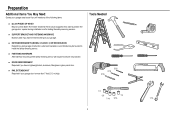
...WOOD BLOCKS Depending upon garage construction, extension brackets or wood blocks may be needed to position the garage door opener during installation and for testing the safety reversing sensors. n RAIL EXTENSION KIT Required if your garage area to the structural supports. n ... HARDWARE Alternate floor mounting of the safety reversing sensor will need any of the following items: n (2) 2X4 PIECES OF WOOD May be used to install the safety reversing sensor. n DOOR REINFORCEMENT Required if you have a finished ceiling in your garage. Tools Needed 5/32 3/16 5/16 1/2 5/8...
...WOOD BLOCKS Depending upon garage construction, extension brackets or wood blocks may be needed to position the garage door opener during installation and for testing the safety reversing sensors. n RAIL EXTENSION KIT Required if your garage area to the structural supports. n ... HARDWARE Alternate floor mounting of the safety reversing sensor will need any of the following items: n (2) 2X4 PIECES OF WOOD May be used to install the safety reversing sensor. n DOOR REINFORCEMENT Required if you have a finished ceiling in your garage. Tools Needed 5/32 3/16 5/16 1/2 5/8...

PD512 Owner Manual
Page 4
...sections) I N K L J O Push button (Model HD210C and LW2200C) or Multi-function control panel (Models PD510 and PD512) O. Save the carton and packing material until the installation and adjustment is packaged in this manual. Curved door arm E. Garage door opener (motor unit) K. Remote control - 1... Button 950ESTD (Models HD210C, PD510, and PD512) or 3 Button 953ESTD (Model LW2200C) P. ...
...sections) I N K L J O Push button (Model HD210C and LW2200C) or Multi-function control panel (Models PD510 and PD512) O. Save the carton and packing material until the installation and adjustment is packaged in this manual. Curved door arm E. Garage door opener (motor unit) K. Remote control - 1... Button 950ESTD (Models HD210C, PD510, and PD512) or 3 Button 953ESTD (Model LW2200C) P. ...
PD512 Owner Manual
Page 5
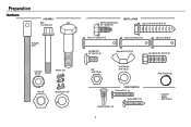
Preparation Hardware ASSEMBLY Bolt Bolt 1/4"-20x1-3/4" Threaded Shaft Lock Nut 1/4"-20 Master Link Nut 3/8" Lock Washer 3/8" Self-Threading Screw 1/4"-14x5/8" (2) INSTALLATION Lag Screw 5/16"-9x1-5/8" (4) Clevis Pin 5/16"x1-1/2" Clevis Pin 5/16"x1-1/4" Clevis Pin 5/16"x1" Carriage Bolt 1/4"-20x1/2" (2) Nut 5/16"-18 (6) Wing Nut 1/4"-20 (2) Lock Washer 5/16"-18 (5) Hex Bolt 5/16"-18x7/8" (4) Ring Fastener (3) DOOR CONTROL Screw 6-32x1" (2) Drywall Anchors (2) Screw 6ABx1" (2) 4 Insulated Staples (Not Shown)
Preparation Hardware ASSEMBLY Bolt Bolt 1/4"-20x1-3/4" Threaded Shaft Lock Nut 1/4"-20 Master Link Nut 3/8" Lock Washer 3/8" Self-Threading Screw 1/4"-14x5/8" (2) INSTALLATION Lag Screw 5/16"-9x1-5/8" (4) Clevis Pin 5/16"x1-1/2" Clevis Pin 5/16"x1-1/4" Clevis Pin 5/16"x1" Carriage Bolt 1/4"-20x1/2" (2) Nut 5/16"-18 (6) Wing Nut 1/4"-20 (2) Lock Washer 5/16"-18 (5) Hex Bolt 5/16"-18x7/8" (4) Ring Fastener (3) DOOR CONTROL Screw 6-32x1" (2) Drywall Anchors (2) Screw 6ABx1" (2) 4 Insulated Staples (Not Shown)
PD512 Owner Manual
Page 6
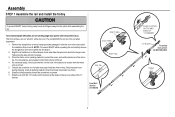
.... If they became loose during shipping, check all the stops on top. Snap them back into place. 3. Assembly STEP 1 Assemble the rail and install the trolley To prevent INJURY from pinching, keep hands and fingers away from the motor unit, as shown. 5. For convenience, put a support under ...the front end of the rail when assembled. 1. To avoid installation difficulties, do so. The front rail has a cut out "window" at the door end. The rail tab MUST be sure there are 4 plastic ...
.... If they became loose during shipping, check all the stops on top. Snap them back into place. 3. Assembly STEP 1 Assemble the rail and install the trolley To prevent INJURY from pinching, keep hands and fingers away from the motor unit, as shown. 5. For convenience, put a support under ...the front end of the rail when assembled. 1. To avoid installation difficulties, do so. The front rail has a cut out "window" at the door end. The rail tab MUST be sure there are 4 plastic ...
PD512 Owner Manual
Page 8
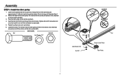
... 3/8" Rail Tab CORRECT INCORRECT Rail Bolt Rail Tab Lock Washer 3/8" Nut 3/8" Grease Inside Pulley Idler Pulley 7 The rail tab is vertical (90º). Assembly STEP 3 Install the idler pulley 1. Lay the chain/cable beside the rail, as shown. 4. Locate the rail tab. Allow it spins freely. 6. Place the idler pulley into...
... 3/8" Rail Tab CORRECT INCORRECT Rail Bolt Rail Tab Lock Washer 3/8" Nut 3/8" Grease Inside Pulley Idler Pulley 7 The rail tab is vertical (90º). Assembly STEP 3 Install the idler pulley 1. Lay the chain/cable beside the rail, as shown. 4. Locate the rail tab. Allow it spins freely. 6. Place the idler pulley into...
PD512 Owner Manual
Page 9
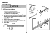
.... Check to make sure the chain is not twisted. (Figure 3) 7. l Securely attach chain spreader BEFORE operating. 1. Connect the cable to the trolley assembly. Assembly STEP 4 Install the chain To avoid possible SERIOUS INJURY to finger from moving garage door opener: l ALWAYS keep hand clear of the pins. Pull the cable around...
.... Check to make sure the chain is not twisted. (Figure 3) 7. l Securely attach chain spreader BEFORE operating. 1. Connect the cable to the trolley assembly. Assembly STEP 4 Install the chain To avoid possible SERIOUS INJURY to finger from moving garage door opener: l ALWAYS keep hand clear of the pins. Pull the cable around...
PD512 Owner Manual
Page 10
... normal. If the chain returns to disconnect the trolley before proceeding to secure the adjustment. Please read the following warnings before adjusting the chain. When installation is too loose. Assembly STEP 5 Tighten the chain 1. You have now finished assembling your garage door opener. This is open, do not re-adjust the... Inner Nut To Tighten Inner Nut Chain Base of Rail 1/4" (6 mm) Mid length of the rail at it's midpoint, retighten the inner nut to the installation section. To tighten the chain, turn the outer nut in the direction shown. 3.
... normal. If the chain returns to disconnect the trolley before proceeding to secure the adjustment. Please read the following warnings before adjusting the chain. When installation is too loose. Assembly STEP 5 Tighten the chain 1. You have now finished assembling your garage door opener. This is open, do not re-adjust the... Inner Nut To Tighten Inner Nut Chain Base of Rail 1/4" (6 mm) Mid length of the rail at it's midpoint, retighten the inner nut to the installation section. To tighten the chain, turn the outer nut in the direction shown. 3.
PD512 Owner Manual
Page 11
... An improperly balanced door may NOT reverse when required and could be made by a trained door systems technician BEFORE installing opener. 4. ALL repairs to garage door control. 11. Install garage door opener 7 feet (2.13 m) or more above the floor and avoiding contact with vehicles to be used ... Unattended devices and features are to avoid accidental release. 7. To avoid SERIOUS PERSONAL INJURY or DEATH from ALL moving parts of 5 feet (1.5 m). Install wall-mounted garage door control: l within reach, but at minimum height of the door. 10. l out of reach of garage door. 12...
... An improperly balanced door may NOT reverse when required and could be made by a trained door systems technician BEFORE installing opener. 4. ALL repairs to garage door control. 11. Install garage door opener 7 feet (2.13 m) or more above the floor and avoiding contact with vehicles to be used ... Unattended devices and features are to avoid accidental release. 7. To avoid SERIOUS PERSONAL INJURY or DEATH from ALL moving parts of 5 feet (1.5 m). Install wall-mounted garage door control: l within reach, but at minimum height of the door. 10. l out of reach of garage door. 12...
PD512 Owner Manual
Page 12
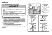
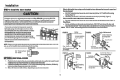
...door and one -piece door without track: pivot hardware Header Wall 8" (20 cm) Highest Door Point of balance. or you need to install the header bracket on a 2x4 (on wall or ceiling), use the maximum height possible, or refer to page 12 for one -piece ... instructions which are under EXTREME tension. Draw an intersecting horizontal line on page 12. 3. l 8" (20 cm) above the high point for ceiling installation. 11 Header Wall Vertical Centerline of Garage Door 2x4 Structural Supports OPTIONAL CEILING MOUNT FOR HEADER BRACKET Unfinished Ceiling Level (Optional) Sectional door...
...door and one -piece door without track: pivot hardware Header Wall 8" (20 cm) Highest Door Point of balance. or you need to install the header bracket on a 2x4 (on wall or ceiling), use the maximum height possible, or refer to page 12 for one -piece ... instructions which are under EXTREME tension. Draw an intersecting horizontal line on page 12. 3. l 8" (20 cm) above the high point for ceiling installation. 11 Header Wall Vertical Centerline of Garage Door 2x4 Structural Supports OPTIONAL CEILING MOUNT FOR HEADER BRACKET Unfinished Ceiling Level (Optional) Sectional door...
PD512 Owner Manual
Page 13
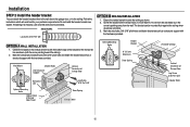
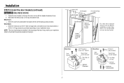
... header bracket You can be mounted flush against the ceiling when clearance is pointing away from the wall. If installing into masonry, use concrete anchors (not provided). The bracket can attach the header bracket either to the wall above the garage door, or to a ... Door Lag Screw 5/16"-9x1-5/8" (Header Wall) Optional Mounting Holes Highest Point of Garage Door Lag Screw 5/16"-9x1-5/8" OPTION B CEILING INSTALLATION 1. Mark the side holes. Do not install the header bracket over drywall. Mark the vertical set of the bracket on the vertical mark, no more than 6" (15 cm) from...
... header bracket You can be mounted flush against the ceiling when clearance is pointing away from the wall. If installing into masonry, use concrete anchors (not provided). The bracket can attach the header bracket either to the wall above the garage door, or to a ... Door Lag Screw 5/16"-9x1-5/8" (Header Wall) Optional Mounting Holes Highest Point of Garage Door Lag Screw 5/16"-9x1-5/8" OPTION B CEILING INSTALLATION 1. Mark the side holes. Do not install the header bracket over drywall. Mark the vertical set of the bracket on the vertical mark, no more than 6" (15 cm) from...
PD512 Owner Manual
Page 14
... ideal for setting the distance between the rail and the door. Have someone hold the opener securely on the garage floor below the header bracket. Installation STEP 3 Attach the rail to secure.
... ideal for setting the distance between the rail and the door. Have someone hold the opener securely on the garage floor below the header bracket. Installation STEP 3 Attach the rail to secure.

PD512 Owner Manual
Page 15
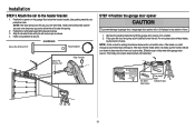
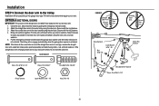
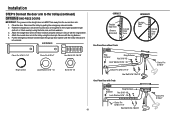
...16"- 18x7/8" Nut 5/16"-18 Hex Bolt 5/16"- 18x7/8" 14 Below are three example installations. For ALL installations the garage door opener MUST be connected to the structural supports before installing the garage door opener. 2. Cut both pieces of each side of the garage door opener ... with the header bracket. On finished ceilings, use the lag screws to attach a support bracket (not provided) to structural supports. Installation STEP 5 Hang the garage door opener To avoid possible SERIOUS INJURY from each hanging bracket to the support bracket with appropriate hardware (not...
...16"- 18x7/8" Nut 5/16"-18 Hex Bolt 5/16"- 18x7/8" 14 Below are three example installations. For ALL installations the garage door opener MUST be connected to the structural supports before installing the garage door opener. 2. Cut both pieces of each side of the garage door opener ... with the header bracket. On finished ceilings, use the lag screws to attach a support bracket (not provided) to structural supports. Installation STEP 5 Hang the garage door opener To avoid possible SERIOUS INJURY from each hanging bracket to the support bracket with appropriate hardware (not...
PD512 Owner Manual
Page 16
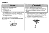
...inch (2.5 cm) from a falling garage door: l If possible, use emergency release handle unless garage doorway is clear of persons and obstructions. Installation STEP 6 Install the light bulb STEP 7 Attach the emergency release rope and handle To prevent possible OVERHEATING of the endpanel or light socket: l DO NOT ... light bulbs. l DO NOT use bulbs larger than 100W. To prevent damage to disengage trolley ONLY when garage door is connected. Install a 100 watt maximum light bulb in the trolley release arm. Tilt towards chassis to avoid entanglement. 15 Weak or broken springs or...
...inch (2.5 cm) from a falling garage door: l If possible, use emergency release handle unless garage doorway is clear of persons and obstructions. Installation STEP 6 Install the light bulb STEP 7 Attach the emergency release rope and handle To prevent possible OVERHEATING of the endpanel or light socket: l DO NOT ... light bulbs. l DO NOT use bulbs larger than 100W. To prevent damage to disengage trolley ONLY when garage door is connected. Install a 100 watt maximum light bulb in the trolley release arm. Tilt towards chassis to avoid entanglement. 15 Weak or broken springs or...
PD512 Owner Manual
Page 17
...factory reinforced doors: l Drill 3/16" fastening holes. Center the door bracket on your door's construction. Mark, drill holes and install as stamped inside the bracket. 2. A horizontal reinforcement brace should cover the height of door bracket. In this case you will ... follows, depending on the previously marked vertical centerline used for opener reinforcement instructions or reinforcement kit. Contact the garage door manufacturer or installing dealer for lightweight garage doors (fiberglass, aluminum, steel, doors with 5/16"-18x2" carriage bolts, lock washers and nuts (not...
...factory reinforced doors: l Drill 3/16" fastening holes. Center the door bracket on your door's construction. Mark, drill holes and install as stamped inside the bracket. 2. A horizontal reinforcement brace should cover the height of door bracket. In this case you will ... follows, depending on the previously marked vertical centerline used for opener reinforcement instructions or reinforcement kit. Contact the garage door manufacturer or installing dealer for lightweight garage doors (fiberglass, aluminum, steel, doors with 5/16"-18x2" carriage bolts, lock washers and nuts (not...
PD512 Owner Manual
Page 18
...Bracket (Finished Ceiling) Door Bracket Optional Placement of Door Bracket Vertical Centerline of Garage Door For a door with no exposed framing, or for the optional installation, use 5/16"-18x2" carriage bolts, lock washers and nuts (not provided) or 5/16"x1-1/2" lag screws (not provided) depending on the top...Placement Hardware (not provided) Top of Door (Inside Garage) Top Edge of the door, in line with the self-threading screws provided. Installation STEP 8 Install the door bracket (continued) OPTION B ONE-PIECE DOORS 1. Mark either the left and right, or the top and bottom holes.
...Bracket (Finished Ceiling) Door Bracket Optional Placement of Door Bracket Vertical Centerline of Garage Door For a door with no exposed framing, or for the optional installation, use 5/16"-18x2" carriage bolts, lock washers and nuts (not provided) or 5/16"x1-1/2" lag screws (not provided) depending on the top...Placement Hardware (not provided) Top of Door (Inside Garage) Top Edge of the door, in line with the self-threading screws provided. Installation STEP 8 Install the door bracket (continued) OPTION B ONE-PIECE DOORS 1. Mark either the left and right, or the top and bottom holes.
PD512 Owner Manual
Page 19
... pulling the emergency release handle. 2. Secure with the ring fastener. 4. Find two pairs of holes that line up and join sections. Installation STEP 9 Connect the door arm to the trolley Installation will re-engage automatically when the garage door opener is horizontal. OPTION A SECTIONAL DOORS IMPORTANT: The groove on the straight door...
... pulling the emergency release handle. 2. Secure with the ring fastener. 4. Find two pairs of holes that line up and join sections. Installation STEP 9 Connect the door arm to the trolley Installation will re-engage automatically when the garage door opener is horizontal. OPTION A SECTIONAL DOORS IMPORTANT: The groove on the straight door...
PD512 Owner Manual
Page 20
Installation STEP 9 Connect the door arm to the door bracket using the clevis pin. Fasten the straight door arm and the curved door arm together to ...
Installation STEP 9 Connect the door arm to the door bracket using the clevis pin. Fasten the straight door arm and the curved door arm together to ...
PD512 Owner Manual
Page 21
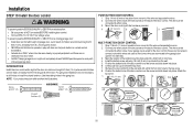
... sight of garage door, out of reach of children at a minimum height of 5 feet (1.5 m) where small children cannot reach, and away from the wall. 5. Install the bottom screw, allowing 1/8 inch (3 mm) to door travel. Remove the door control from the wall and drill a 5/32 inch (4 mm) hole for the...wires to connect, note which wires are used so the correct wires are no obstructions to protrude from the moving parts of door. Installation STEP 10 Install the door control To prevent possible SERIOUS INJURY or DEATH from ALL moving parts of the door. Lift the push bar up and ...
... sight of garage door, out of reach of children at a minimum height of 5 feet (1.5 m) where small children cannot reach, and away from the wall. 5. Install the bottom screw, allowing 1/8 inch (3 mm) to door travel. Remove the door control from the wall and drill a 5/32 inch (4 mm) hole for the...wires to connect, note which wires are used so the correct wires are no obstructions to protrude from the moving parts of door. Installation STEP 10 Install the door control To prevent possible SERIOUS INJURY or DEATH from ALL moving parts of the door. Lift the push bar up and ...
