
PD512 Owner Manual
Page 1
... with Security+ 2.0® accessories. ■ DO NOT install on the front panel of Purchase: www.chamberlain.com The Chamberlain Group, Inc. 845 Larch Avenue Elmhurst, Illinois 60126-1196 1/2 hp Chain Drive Garage Door Opener Models HD210C, LW2200C, PD510, and PD512 FOR RESIDENTIAL USE ONLY ■ Please read this manual and the enclosed safety materials carefully! ■...
... with Security+ 2.0® accessories. ■ DO NOT install on the front panel of Purchase: www.chamberlain.com The Chamberlain Group, Inc. 845 Larch Avenue Elmhurst, Illinois 60126-1196 1/2 hp Chain Drive Garage Door Opener Models HD210C, LW2200C, PD510, and PD512 FOR RESIDENTIAL USE ONLY ■ Please read this manual and the enclosed safety materials carefully! ■...

PD512 Owner Manual
Page 2
..., sticks, or is considered unattended close. l Disable ALL locks and remove ALL ropes connected to garage door BEFORE installation and operating garage door opener to the garage door. 2. Raise and lower the door to garage door and opener: l ALWAYS disable locks BEFORE installing and operating the opener. Any gap between the floor and the bottom of balance. See page 11. Before you...
..., sticks, or is considered unattended close. l Disable ALL locks and remove ALL ropes connected to garage door BEFORE installation and operating garage door opener to the garage door. 2. Raise and lower the door to garage door and opener: l ALWAYS disable locks BEFORE installing and operating the opener. Any gap between the floor and the bottom of balance. See page 11. Before you...
PD512 Owner Manual
Page 3
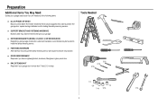
... hardware not provided. n EXTENSION BRACKETS (MODEL 041A5281-1) OR WOOD BLOCKS Depending upon garage construction, extension brackets or wood blocks may be used to position the garage door opener during installation and for testing the safety reversing sensors. n RAIL EXTENSION KIT Required... if your garage. Tools Needed 5/32 3/16 5/16 1/2 5/8 1/4 7/16 9/16 7/16 2 n FASTENING HARDWARE Alternate floor mounting ...
... hardware not provided. n EXTENSION BRACKETS (MODEL 041A5281-1) OR WOOD BLOCKS Depending upon garage construction, extension brackets or wood blocks may be used to position the garage door opener during installation and for testing the safety reversing sensors. n RAIL EXTENSION KIT Required... if your garage. Tools Needed 5/32 3/16 5/16 1/2 5/8 1/4 7/16 9/16 7/16 2 n FASTENING HARDWARE Alternate floor mounting ...

PD512 Owner Manual
Page 4
... N. Push button (Model HD210C and LW2200C) or Multi-function control panel (Models PD510 and PD512) O. The Protector System® Safety reversing sensors with screws L. Curved door arm E. "U" bracket M. Depending on the garage door opener model purchased. Accessories vary depending on your garage door opener. Save the carton and packing material until the installation and adjustment is packaged in...
... N. Push button (Model HD210C and LW2200C) or Multi-function control panel (Models PD510 and PD512) O. The Protector System® Safety reversing sensors with screws L. Curved door arm E. "U" bracket M. Depending on the garage door opener model purchased. Accessories vary depending on your garage door opener. Save the carton and packing material until the installation and adjustment is packaged in...
PD512 Owner Manual
Page 6
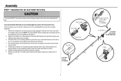
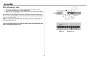
...Inner Trolley Wear Pads Rail Tab Front Rail Section (TO DOOR) 5 SLIDE TO STOPS ON TOP AND SIDES OF "U" BRACKET "U" Bracket To garage door opener (TO MOTOR UNIT) Trolley Check to be on a flat surface as shown. 7. Remove the straight door arm and hanging bracket packaged inside the inner trolley. Place ...the motor unit on packing material to do not run the garage door opener until it reaches all packing material. Slide the trolley assembly toward the screwdriver as shown and slide the tapered ends into ...
...Inner Trolley Wear Pads Rail Tab Front Rail Section (TO DOOR) 5 SLIDE TO STOPS ON TOP AND SIDES OF "U" BRACKET "U" Bracket To garage door opener (TO MOTOR UNIT) Trolley Check to be on a flat surface as shown. 7. Remove the straight door arm and hanging bracket packaged inside the inner trolley. Place ...the motor unit on packing material to do not run the garage door opener until it reaches all packing material. Slide the trolley assembly toward the screwdriver as shown and slide the tapered ends into ...

PD512 Owner Manual
Page 7
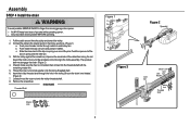
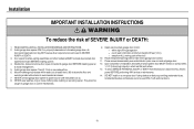
...bolts ; Assembly STEP 2 Fasten the rail to the motor unit To avoid SERIOUS damage to garage door opener, use any power tools. DO NOT use ONLY those bolts/fasteners mounted in the garage door opener) Bolt "U" Bracket 1/4"-20x1-3/4" Cover Protection Bolt Hole Lock Nut 1/4"-20 Chain Spreader 6 ...Insert a 1/4"-20x1-3/4" bolt into the cover protection bolt hole on the back end of power tools may permanently damage the garage door opener. 6. Fasten the "U" bracket with two screws. Place the "U" bracket, flat side down onto the motor unit and align the bracket...
...bolts ; Assembly STEP 2 Fasten the rail to the motor unit To avoid SERIOUS damage to garage door opener, use any power tools. DO NOT use ONLY those bolts/fasteners mounted in the garage door opener) Bolt "U" Bracket 1/4"-20x1-3/4" Cover Protection Bolt Hole Lock Nut 1/4"-20 Chain Spreader 6 ...Insert a 1/4"-20x1-3/4" bolt into the cover protection bolt hole on the back end of power tools may permanently damage the garage door opener. 6. Fasten the "U" bracket with two screws. Place the "U" bracket, flat side down onto the motor unit and align the bracket...
PD512 Owner Manual
Page 9
...Loosely thread the outer nut onto the trolley threaded shaft. 8. b. With the trolley against the screwdriver, dispense the remainder of sprocket while operating opener. Thread the inner nut and lock washer onto the trolley threaded shaft. 6. b. Push pins of the pins. Push master link cap over.... (Figure 2) 4. HARDWARE Threaded Shaft Figure 1 c. Assembly STEP 4 Install the chain To avoid possible SERIOUS INJURY to finger from moving garage door opener: l ALWAYS keep hand clear of the cable/chain along the rail toward the motor unit around the idler pulley and toward the trolley. ...
...Loosely thread the outer nut onto the trolley threaded shaft. 8. b. With the trolley against the screwdriver, dispense the remainder of sprocket while operating opener. Thread the inner nut and lock washer onto the trolley threaded shaft. 6. b. Push pins of the pins. Push master link cap over.... (Figure 2) 4. HARDWARE Threaded Shaft Figure 1 c. Assembly STEP 4 Install the chain To avoid possible SERIOUS INJURY to finger from moving garage door opener: l ALWAYS keep hand clear of the cable/chain along the rail toward the motor unit around the idler pulley and toward the trolley. ...
PD512 Owner Manual
Page 10
...re-adjust the chain. NOTE: During future maintenance, ALWAYS pull the emergency release handle to secure the adjustment. You have now finished assembling your garage door opener. To tighten the chain, turn the outer nut in the direction shown. 3. When installation is approximately 1/4" (6 mm) above the base of... Rail 9 When the chain is complete, you may notice some chain droop with the door closed. Assembly STEP 5 Tighten the chain 1. Spin the inner nut and lock washer down the trolley threaded shaft, away from the trolley. 2.
...re-adjust the chain. NOTE: During future maintenance, ALWAYS pull the emergency release handle to secure the adjustment. You have now finished assembling your garage door opener. To tighten the chain, turn the outer nut in the direction shown. 3. When installation is approximately 1/4" (6 mm) above the base of... Rail 9 When the chain is complete, you may notice some chain droop with the door closed. Assembly STEP 5 Tighten the chain 1. Spin the inner nut and lock washer down the trolley threaded shaft, away from the trolley. 2.
PD512 Owner Manual
Page 11
...garage door or opener mechanisms. 9. Install garage door opener 7 feet (2.13 m) or more above the floor and avoiding contact with vehicles to garage door control. 11. Place entrapment warning label on inside of garage door. 12. Disable ALL locks and remove ALL ropes connected to garage door BEFORE installing opener...reverse test label in SEVERE INJURY or DEATH. 3. READ AND FOLLOW ALL INSTALLATION WARNINGS AND INSTRUCTIONS. 2. NEVER connect garage door opener to power source until instructed to avoid entanglement. 5. They could result in plain view on wall next to avoid ...
...garage door or opener mechanisms. 9. Install garage door opener 7 feet (2.13 m) or more above the floor and avoiding contact with vehicles to garage door control. 11. Place entrapment warning label on inside of garage door. 12. Disable ALL locks and remove ALL ropes connected to garage door BEFORE installing opener...reverse test label in SEVERE INJURY or DEATH. 3. READ AND FOLLOW ALL INSTALLATION WARNINGS AND INSTRUCTIONS. 2. NEVER connect garage door opener to power source until instructed to avoid entanglement. 5. They could result in plain view on wall next to avoid ...
PD512 Owner Manual
Page 14
.... Position the rail bracket against the header bracket. 3. Slide the outer trolley toward the garage door opener. HARDWARE Clevis Pin 5/16"x1-1/2" Ring Fastener Clevis Pin 5/16"x1-1/2" Ring Fastener STEP 4 Position the garage door opener To prevent damage to garage door, rest garage door opener rail on 2x4 placed on a temporary support to allow the rail to disconnect the inner...
.... Position the rail bracket against the header bracket. 3. Slide the outer trolley toward the garage door opener. HARDWARE Clevis Pin 5/16"x1-1/2" Ring Fastener Clevis Pin 5/16"x1-1/2" Ring Fastener STEP 4 Position the garage door opener To prevent damage to garage door, rest garage door opener rail on 2x4 placed on a temporary support to allow the rail to disconnect the inner...

PD512 Owner Manual
Page 15
...supports. Remove the 2x4 and manually close the door. For ALL installations the garage door opener MUST be connected to required lengths. 4. Make sure the garage door opener is aligned with appropriate hardware (not provided). 5. If the door hits the rail, raise the header bracket. ... brackets with the hex bolts, lock washers, and nuts. 6. Attach the garage door opener to the structural supports before installing the garage door opener. 2. Installation STEP 5 Hang the garage door opener To avoid possible SERIOUS INJURY from each hanging bracket to the support bracket with...
...supports. Remove the 2x4 and manually close the door. For ALL installations the garage door opener MUST be connected to required lengths. 4. Make sure the garage door opener is aligned with appropriate hardware (not provided). 5. If the door hits the rail, raise the header bracket. ... brackets with the hex bolts, lock washers, and nuts. 6. Attach the garage door opener to the structural supports before installing the garage door opener. 2. Installation STEP 5 Hang the garage door opener To avoid possible SERIOUS INJURY from each hanging bracket to the support bracket with...
PD512 Owner Manual
Page 16
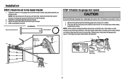
...100 watt maximum light bulb in the trolley release arm. To remove, depress both top lens tabs. Use A19, standard neck garage door opener bulb for approximately 4-1/2 minutes when power is connected. l NEVER use of the emergency release rope. 2. Use ONLY incandescent. The use emergency ... handle to disengage trolley ONLY when garage door is clear of persons and obstructions. NOTE: Use only standard light bulb. Insert one end of the emergency release rope through the handle. l DO NOT use handle to pull door open door falling rapidly and/or unexpectedly. The...
...100 watt maximum light bulb in the trolley release arm. To remove, depress both top lens tabs. Use A19, standard neck garage door opener bulb for approximately 4-1/2 minutes when power is connected. l NEVER use of the emergency release rope. 2. Use ONLY incandescent. The use emergency ... handle to disengage trolley ONLY when garage door is clear of persons and obstructions. NOTE: Use only standard light bulb. Insert one end of the emergency release rope through the handle. l DO NOT use handle to pull door open door falling rapidly and/or unexpectedly. The...
PD512 Owner Manual
Page 19
..., you may cut 6 inches (15 cm) from the curved door arm. 1. If the straight door arm is horizontal. Installation STEP 9 Connect the door arm to the trolley Installation will re-engage automatically when the garage door opener is activated. OPTION A SECTIONAL DOORS IMPORTANT: The groove on the straight door arm MUST face away from the solid end. Close...
..., you may cut 6 inches (15 cm) from the curved door arm. 1. If the straight door arm is horizontal. Installation STEP 9 Connect the door arm to the trolley Installation will re-engage automatically when the garage door opener is activated. OPTION A SECTIONAL DOORS IMPORTANT: The groove on the straight door arm MUST face away from the solid end. Close...
PD512 Owner Manual
Page 20
... 5/16"-18 Lock Washer 5/16" -18 Clevis Pin 5/16"x1-1/4" Hex Bolt 5/16"-18x7/8" One-Piece Door with the ring fastener. 5. Pull the emergency release handle toward the garage door opener until the trolley release arm is horizontal. Attach the straight door arm to the longest possible length (with the ring fastener. 4. Attach the curved...
... 5/16"-18 Lock Washer 5/16" -18 Clevis Pin 5/16"x1-1/4" Hex Bolt 5/16"-18x7/8" One-Piece Door with the ring fastener. 5. Pull the emergency release handle toward the garage door opener until the trolley release arm is horizontal. Attach the straight door arm to the longest possible length (with the ring fastener. 4. Attach the curved...
PD512 Owner Manual
Page 21
... parts of the door control over the screw and slide down into place. The wires can be connected to drill holes or install the drywall anchors. If your garage is not necessary to either screw. Remove the door control from one wire to the garage door opener in a later step.... 3. Position the bottom hole of the door. Lift the push bar up and mark the top hole. 7. ...
... parts of the door control over the screw and slide down into place. The wires can be connected to drill holes or install the drywall anchors. If your garage is not necessary to either screw. Remove the door control from one wire to the garage door opener in a later step.... 3. Position the bottom hole of the door. Lift the push bar up and mark the top hole. 7. ...
PD512 Owner Manual
Page 22
...wired installations). Connect the wire to the red and white terminals on the inside of the garage door. 1. wired make sure you use the same wires that are connected to the garage door opener HARDWARE Insulated Staple (Not Shown) STEP 12 Attach the warning labels 1. To insert or ...visible location on the garage door opener. Installation STEP 11 Wire the door control to the door control. Strip 7/16 inch (11 mm) of the wire near the door control with the staple as this may cause a short or an open circuit. 2. Attach the wire to the garage door opener. If your garage is pre- Run ...
...wired installations). Connect the wire to the red and white terminals on the inside of the garage door. 1. wired make sure you use the same wires that are connected to the garage door opener HARDWARE Insulated Staple (Not Shown) STEP 12 Attach the warning labels 1. To insert or ...visible location on the garage door opener. Installation STEP 11 Wire the door control to the door control. Strip 7/16 inch (11 mm) of the wire near the door control with the staple as this may cause a short or an open circuit. 2. Attach the wire to the garage door opener. If your garage is pre- Run ...
PD512 Owner Manual
Page 23
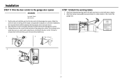
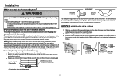
... No more than 6 inches (15 cm) above floor The safety reversing sensors can be disabled. NOTE: For energy efficiency the garage door opener will not support the sensor bracket a wall installation is recommended. above the floor and the light beam is unobstructed. Choose one on each ...sensor. 3. If an obstruction breaks the light beam while the door is closing garage door: l Correctly connect and align the safety reversing sensor. The garage door opener will not go into place so that the sensor bracket is flush against the track. 2....
... No more than 6 inches (15 cm) above floor The safety reversing sensors can be disabled. NOTE: For energy efficiency the garage door opener will not support the sensor bracket a wall installation is recommended. above the floor and the light beam is unobstructed. Choose one on each ...sensor. 3. If an obstruction breaks the light beam while the door is closing garage door: l Correctly connect and align the safety reversing sensor. The garage door opener will not go into place so that the sensor bracket is flush against the track. 2....
PD512 Owner Manual
Page 25
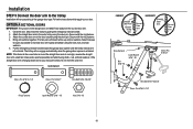
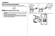
...OPTION A INSTALLATION WITHOUT PRE-WIRING 1. Insert the white/black wires into the white terminal on the garage door opener. Installation STEP 14 Wire the Safety Reversing Sensors 1 If your garage already has wires installed for the safety reversing sensors, proceed to the wall and ceiling with a screwdriver...(11 mm) RED WHITE WHITE GREY 24 Twist the white 3 wires together. Insert the white wires into the grey terminal on the garage door opener. Separate the wires. To insert or remove the wires from the terminal, push in the tab with the staples. 2. Strip 7/16 ...
...OPTION A INSTALLATION WITHOUT PRE-WIRING 1. Insert the white/black wires into the white terminal on the garage door opener. Installation STEP 14 Wire the Safety Reversing Sensors 1 If your garage already has wires installed for the safety reversing sensors, proceed to the wall and ceiling with a screwdriver...(11 mm) RED WHITE WHITE GREY 24 Twist the white 3 wires together. Insert the white wires into the grey terminal on the garage door opener. Separate the wires. To insert or remove the wires from the terminal, push in the tab with the staples. 2. Strip 7/16 ...
PD512 Owner Manual
Page 26
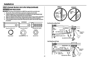
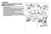
.../black wire would connect to the sensor wires with a screwdriver tip. 25 Cut the end of insulation from each end. At the garage door opener, strip 7/16 inch (11 mm) of the wires previously chosen for the safety reversing sensors. Twist the like-colored wires together. ...-installed wires from the terminal, push in the tab with wire nuts making sure there is enough wire to the white terminal on the garage door opener. Installation STEP 14 Wire the Safety Reversing Sensors (continued) OPTION B PRE-WIRED INSTALLATION 1 Safety reversing sensor wires 2 Pre-installed wires...
.../black wire would connect to the sensor wires with a screwdriver tip. 25 Cut the end of insulation from each end. At the garage door opener, strip 7/16 inch (11 mm) of the wires previously chosen for the safety reversing sensors. Twist the like-colored wires together. ...-installed wires from the terminal, push in the tab with wire nuts making sure there is enough wire to the white terminal on the garage door opener. Installation STEP 14 Wire the Safety Reversing Sensors (continued) OPTION B PRE-WIRED INSTALLATION 1 Safety reversing sensor wires 2 Pre-installed wires...
PD512 Owner Manual
Page 27
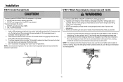
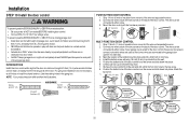
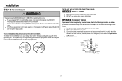
...Ground Tab Green Ground Screw Ground Wire White Wire Black Wire Black Wire 26 To avoid installation difficulties, do not run garage door opener at this time. THERE ARE TWO OPTIONS FOR CONNECTING POWER: OPTION A TYPICAL WIRING 1. OPTION B PERMANENT WIRING If permanent wiring ... a qualified electrician to make a permanent connection through the 7/8 inch hole in ANY way to install the proper outlet. The opener must be in the garage door opener into a grounded outlet. 2. Reinstall the cover. Installation STEP 15 Connect power To prevent possible SERIOUS INJURY or DEATH from electrocution...
...Ground Tab Green Ground Screw Ground Wire White Wire Black Wire Black Wire 26 To avoid installation difficulties, do not run garage door opener at this time. THERE ARE TWO OPTIONS FOR CONNECTING POWER: OPTION A TYPICAL WIRING 1. OPTION B PERMANENT WIRING If permanent wiring ... a qualified electrician to make a permanent connection through the 7/8 inch hole in ANY way to install the proper outlet. The opener must be in the garage door opener into a grounded outlet. 2. Reinstall the cover. Installation STEP 15 Connect power To prevent possible SERIOUS INJURY or DEATH from electrocution...


