
PD752KEV Owners Manual Manual
Page 1
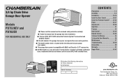
...and Security+ 2.0™ accessories. ■ DO NOT install on a one-piece door if using devices or features providing unattended close. 3/4 hp Chain Drive Garage Door Opener Models PD752KEV and PD762EV FOR RESIDENTIAL USE ONLY ■ Please read this manual and the enclosed safety ...Date of the garage door opener are to ensure safe operation. ■ The model number label is located on the left side panel of your garage door opener. ■ This garage door opener is connected and properly aligned. ■ Periodic checks of Purchase: www.chamberlain.com The Chamberlain Group, Inc. ...
...and Security+ 2.0™ accessories. ■ DO NOT install on a one-piece door if using devices or features providing unattended close. 3/4 hp Chain Drive Garage Door Opener Models PD752KEV and PD762EV FOR RESIDENTIAL USE ONLY ■ Please read this manual and the enclosed safety ...Date of the garage door opener are to ensure safe operation. ■ The model number label is located on the left side panel of your garage door opener. ■ This garage door opener is connected and properly aligned. ■ Periodic checks of Purchase: www.chamberlain.com The Chamberlain Group, Inc. ...
PD752KEV Owners Manual Manual
Page 2
... m) to offer safe service provided it . Read the warnings carefully. l Disable ALL locks and remove ALL ropes connected to garage door BEFORE installation and operating garage door opener to avoid malfunction and damage. Read them . Disable locks and remove any other MyQ® devices are under EXTREME tension. ... of serious injury or death if you to the possibility of the door is a torsion spring or center bearing plate in strict accordance with sectional doors . If your garage door and/or the garage door opener if you do not comply with the warnings that accompany it is ...
... m) to offer safe service provided it . Read the warnings carefully. l Disable ALL locks and remove ALL ropes connected to garage door BEFORE installation and operating garage door opener to avoid malfunction and damage. Read them . Disable locks and remove any other MyQ® devices are under EXTREME tension. ... of serious injury or death if you to the possibility of the door is a torsion spring or center bearing plate in strict accordance with sectional doors . If your garage door and/or the garage door opener if you do not comply with the warnings that accompany it is ...
PD752KEV Owners Manual Manual
Page 3
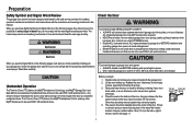
...13 m) high. Preparation Additional Items You May Need: Survey your garage area to see if you will require hardware not provided. n SUPPORT BRACKET AND FASTENING HARDWARE Must be used to position the garage door opener during installation and for testing the safety reversing sensors. n EXTENSION... BRACKETS (MODEL 041A5281-1) OR WOOD BLOCKS Depending upon garage construction, extension brackets or wood blocks may be needed to the...
...13 m) high. Preparation Additional Items You May Need: Survey your garage area to see if you will require hardware not provided. n SUPPORT BRACKET AND FASTENING HARDWARE Must be used to position the garage door opener during installation and for testing the safety reversing sensors. n EXTENSION... BRACKETS (MODEL 041A5281-1) OR WOOD BLOCKS Depending upon garage construction, extension brackets or wood blocks may be needed to the...

PD752KEV Owners Manual Manual
Page 4
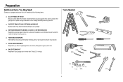
... brackets (2) (Packaged inside front rail section) F. Depending on the garage door opener model purchased. A. Header bracket B. Door control O. Save the carton and packing material until the installation and adjustment is packaged in this manual. Curved door arm E. Garage door opener (motor unit) K. "U" bracket M. Instructions for reference only and your garage door opener. Accessories vary depending on your model, other accessories may...
... brackets (2) (Packaged inside front rail section) F. Depending on the garage door opener model purchased. A. Header bracket B. Door control O. Save the carton and packing material until the installation and adjustment is packaged in this manual. Curved door arm E. Garage door opener (motor unit) K. "U" bracket M. Instructions for reference only and your garage door opener. Accessories vary depending on your model, other accessories may...
PD752KEV Owners Manual Manual
Page 6
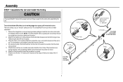
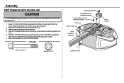
... away from the motor unit, as shown. 5. Inner Trolley Wear Pads Rail Tab Front Rail Section (TO DOOR) 5 SLIDE TO STOPS ON TOP AND SIDES OF "U" BRACKET "U" Bracket To garage door opener (TO MOTOR UNIT) Trolley If they became loose during shipping, check all the stops on top of the rail.... 4. Outer Trolley To avoid installation difficulties, do so. Place the motor unit on packing material to do not run the garage door opener until it reaches all packing material. The rail tab MUST be sure there are 4 plastic wear pads inside the front rail and set ...
... away from the motor unit, as shown. 5. Inner Trolley Wear Pads Rail Tab Front Rail Section (TO DOOR) 5 SLIDE TO STOPS ON TOP AND SIDES OF "U" BRACKET "U" Bracket To garage door opener (TO MOTOR UNIT) Trolley If they became loose during shipping, check all the stops on top of the rail.... 4. Outer Trolley To avoid installation difficulties, do so. Place the motor unit on packing material to do not run the garage door opener until it reaches all packing material. The rail tab MUST be sure there are 4 plastic wear pads inside the front rail and set ...
PD752KEV Owners Manual Manual
Page 7
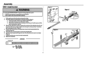
...as shown. Insert a 1/4"-20x1-3/4" bolt into the cover protection bolt hole on the back end of power tools may permanently damage the garage door opener. 6. Place the "U" bracket, flat side down onto the motor unit and align the bracket holes with the previously removed bolt and...nut; HARDWARE Hex Screws 8-32x7/16 Bolt (Mounted in the garage door opener) Lock Nut (Mounted in the top of the opener. 1. Fasten the "U" bracket with the bolt holes. 5. DO NOT use ONLY those bolts/fasteners mounted in the garage door opener) "U" Bracket Bolt 1/4"-20x1-3/4" Cover Protection Bolt Hole Bolt 1/4"-...
...as shown. Insert a 1/4"-20x1-3/4" bolt into the cover protection bolt hole on the back end of power tools may permanently damage the garage door opener. 6. Place the "U" bracket, flat side down onto the motor unit and align the bracket holes with the previously removed bolt and...nut; HARDWARE Hex Screws 8-32x7/16 Bolt (Mounted in the garage door opener) Lock Nut (Mounted in the top of the opener. 1. Fasten the "U" bracket with the bolt holes. 5. DO NOT use ONLY those bolts/fasteners mounted in the garage door opener) "U" Bracket Bolt 1/4"-20x1-3/4" Cover Protection Bolt Hole Bolt 1/4"-...
PD752KEV Owners Manual Manual
Page 9
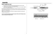
... the inner nut and lock washer onto the trolley threaded shaft. 6. Remove the screwdriver. Connect the cable to finger from moving garage door opener: l ALWAYS keep hand clear of the pins. Loosely thread the outer nut onto the trolley threaded shaft. 8. c. Push the... connect it to the trolley assembly. l Securely attach chain spreader BEFORE operating. 1. b. Push master link cap over one of sprocket while operating opener. Figure 3 Master Link 8 Figure 2 Sprocket Outer Nut Master Link Inner Lock Nut Washer Master Link Threaded Shaft Slide the closed end of the...
... the inner nut and lock washer onto the trolley threaded shaft. 6. Remove the screwdriver. Connect the cable to finger from moving garage door opener: l ALWAYS keep hand clear of the pins. Loosely thread the outer nut onto the trolley threaded shaft. 8. c. Push the... connect it to the trolley assembly. l Securely attach chain spreader BEFORE operating. 1. b. Push master link cap over one of sprocket while operating opener. Figure 3 Master Link 8 Figure 2 Sprocket Outer Nut Master Link Inner Lock Nut Washer Master Link Threaded Shaft Slide the closed end of the...
PD752KEV Owners Manual Manual
Page 10
...base of Rail 9 You have now finished assembling your garage door opener. NOTE: During future maintenance, ALWAYS pull the emergency release handle to the position shown when the door is complete, you may notice some chain droop with the door closed. Please read the following warnings before adjusting the chain.... When installation is open, do not re-adjust the chain. Spin the inner ...
...base of Rail 9 You have now finished assembling your garage door opener. NOTE: During future maintenance, ALWAYS pull the emergency release handle to the position shown when the door is complete, you may notice some chain droop with the door closed. Please read the following warnings before adjusting the chain.... When installation is open, do not re-adjust the chain. Spin the inner ...
PD752KEV Owners Manual Manual
Page 11
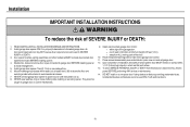
... so. 8. Mount the emergency release within sight of 5 feet (1.5 m). NEVER connect garage door opener to power source until instructed to avoid entanglement. 5. l out of reach of garage door. 12. Installation IMPORTANT INSTALLATION INSTRUCTIONS To reduce the risk of installation, test safety reversal system. Install garage door opener 7 feet (2.13 m) or more above the floor and avoiding contact with...
... so. 8. Mount the emergency release within sight of 5 feet (1.5 m). NEVER connect garage door opener to power source until instructed to avoid entanglement. 5. l out of reach of garage door. 12. Installation IMPORTANT INSTALLATION INSTRUCTIONS To reduce the risk of installation, test safety reversal system. Install garage door opener 7 feet (2.13 m) or more above the floor and avoiding contact with...
PD752KEV Owners Manual Manual
Page 14
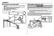
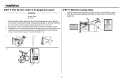
... this point. Remove the packing material and lift the garage door opener onto a ladder. 2. Installation STEP 3 Attach the rail to garage door, rest garage door opener rail on 2x4 placed on top section of door. 1. Slide the outer trolley toward the garage door opener. Position the rail bracket against the header bracket. 3. Fully open the door and place a 2x4 (laid flat) under the rail...
... this point. Remove the packing material and lift the garage door opener onto a ladder. 2. Installation STEP 3 Attach the rail to garage door, rest garage door opener rail on 2x4 placed on top section of door. 1. Slide the outer trolley toward the garage door opener. Position the rail bracket against the header bracket. 3. Fully open the door and place a 2x4 (laid flat) under the rail...
PD752KEV Owners Manual Manual
Page 15
... MUST be different. Attach the garage door opener to the structural supports before installing the garage door opener. 2. For ALL installations the garage door opener MUST be connected to the support bracket. 3. Make sure the garage door opener is aligned with appropriate hardware (not provided). 5. Remove the 2x4 and manually close the door. Installation STEP 5 Hang the garage door opener To avoid possible SERIOUS INJURY from...
... MUST be different. Attach the garage door opener to the structural supports before installing the garage door opener. 2. For ALL installations the garage door opener MUST be connected to the support bracket. 3. Make sure the garage door opener is aligned with appropriate hardware (not provided). 5. Remove the 2x4 and manually close the door. Installation STEP 5 Hang the garage door opener To avoid possible SERIOUS INJURY from...
PD752KEV Owners Manual Manual
Page 19
... using the bolts, nuts, and lock washers. 5. Find two pairs of holes that line up and join sections. Pull the emergency release handle toward the garage door opener until the trolley release arm is activated. Secure with the ring fastener. 3. Select holes as far apart as possible) and attach using the clevis pin...
... using the bolts, nuts, and lock washers. 5. Find two pairs of holes that line up and join sections. Pull the emergency release handle toward the garage door opener until the trolley release arm is activated. Secure with the ring fastener. 3. Select holes as far apart as possible) and attach using the clevis pin...
PD752KEV Owners Manual Manual
Page 20
.../8" 19 Clevis Pin 5/16"x1" Clevis Pin 5/16"x1" Attach the curved door arm to the trolley (continued) OPTION B ONE-PIECE DOORS IMPORTANT: The groove on the straight door arm MUST face away from the curved door arm. 1. Pull the emergency release handle toward the garage door opener until the trolley release arm is horizontal. Close the...
.../8" 19 Clevis Pin 5/16"x1" Clevis Pin 5/16"x1" Attach the curved door arm to the trolley (continued) OPTION B ONE-PIECE DOORS IMPORTANT: The groove on the straight door arm MUST face away from the curved door arm. 1. Pull the emergency release handle toward the garage door opener until the trolley release arm is horizontal. Close the...
PD752KEV Owners Manual Manual
Page 21
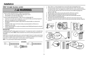
... INJURY or DEATH from a closing garage door. NOTE: Older Chamberlain door controls and third party products are connected to the garage door opener in the gang box. NOTE: Your product may look different than the illustrations. Remove the door control from electrocution: l Be sure power is NOT connected BEFORE installing door control. Your garage door opener is not necessary to cross path...
... INJURY or DEATH from a closing garage door. NOTE: Older Chamberlain door controls and third party products are connected to the garage door opener in the gang box. NOTE: Your product may look different than the illustrations. Remove the door control from electrocution: l Be sure power is NOT connected BEFORE installing door control. Your garage door opener is not necessary to cross path...
PD752KEV Owners Manual Manual
Page 22
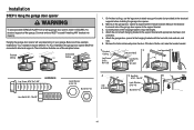
... Shown) STEP 12 Attach the warning labels 1. Installation STEP 11 Wire the door control to the red and white terminals on the garage door opener. Attach the entrapment warning label on the inside of the garage door. 1. If your garage is pre- Attach the wire to the wall and ceiling with tacks or ...staples. 2. To insert or release wires from the terminal, push in a visible location on the wall near the garage door opener. 3. Do not pierce the wire with screwdriver tip. 1 2 7/16" (11 mm) Staple 3 RED WHITE WHITE GREY 21 wired make sure ...
... Shown) STEP 12 Attach the warning labels 1. Installation STEP 11 Wire the door control to the red and white terminals on the garage door opener. Attach the entrapment warning label on the inside of the garage door. 1. If your garage is pre- Attach the wire to the wall and ceiling with tacks or ...staples. 2. To insert or release wires from the terminal, push in a visible location on the wall near the garage door opener. 3. Do not pierce the wire with screwdriver tip. 1 2 7/16" (11 mm) Staple 3 RED WHITE WHITE GREY 21 wired make sure ...
PD752KEV Owners Manual Manual
Page 23
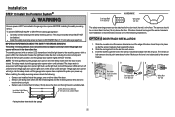
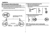
...MUST NOT be connected and aligned correctly before the garage door opener will stop and reverse to the garage door opener BEFORE installing the safety reversing sensor. NOTE: For energy efficiency the garage door opener will enter sleep mode when the door is not obstructed by the sensor bracket. 1 2... should point toward each other . The garage door opener will turn off and whenever the garage door opener lights turn on either side of the following : l Sensors are facing each other with the garage door opener light bulb; OPTION A DOOR TRACK INSTALLATION 1. Slide the curved arms ...
...MUST NOT be connected and aligned correctly before the garage door opener will stop and reverse to the garage door opener BEFORE installing the safety reversing sensor. NOTE: For energy efficiency the garage door opener will enter sleep mode when the door is not obstructed by the sensor bracket. 1 2... should point toward each other . The garage door opener will turn off and whenever the garage door opener lights turn on either side of the following : l Sensors are facing each other with the garage door opener light bulb; OPTION A DOOR TRACK INSTALLATION 1. Slide the curved arms ...
PD752KEV Owners Manual Manual
Page 25
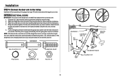
Strip 7/16 inch (11 mm) of wires. Insert the white wires into the grey terminal on the garage door opener. To insert or remove the wires from each set of insulation from the terminal, push in the tab with the staples. 2. Separate the wires.... Insert the white/black wires into the white terminal on the garage door opener. HARDWARE 2 Staple Insulated Staple (Not Shown) OPTION A INSTALLATION WITHOUT PRE-WIRING 1. Run the wire from both sensors to the wall and ceiling with a ...
Strip 7/16 inch (11 mm) of wires. Insert the white wires into the grey terminal on the garage door opener. To insert or remove the wires from each set of insulation from the terminal, push in the tab with the staples. 2. Separate the wires.... Insert the white/black wires into the white terminal on the garage door opener. HARDWARE 2 Staple Insulated Staple (Not Shown) OPTION A INSTALLATION WITHOUT PRE-WIRING 1. Run the wire from both sensors to the wall and ceiling with a ...
PD752KEV Owners Manual Manual
Page 26
...(for the safety reversing sensors. Make sure that are connected to the white/black safety sensor wires to the white terminal on the garage door opener. At the garage door opener, strip 7/16 inch (11 mm) of insulation from each end of the safety reversing sensor wire, making sure the colors 3 ...11 mm) of insulation from each end. Insert the wires connected to the white safety sensor wires to the grey terminal on the garage door opener. For example, the white wire would connect to the yellow wire and the white/black wire would connect to reach the pre-...
...(for the safety reversing sensors. Make sure that are connected to the white/black safety sensor wires to the white terminal on the garage door opener. At the garage door opener, strip 7/16 inch (11 mm) of insulation from each end of the safety reversing sensor wire, making sure the colors 3 ...11 mm) of insulation from each end. Insert the wires connected to the white safety sensor wires to the grey terminal on the garage door opener. For example, the white wire would connect to the yellow wire and the white/black wire would connect to reach the pre-...
PD752KEV Owners Manual Manual
Page 27
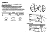
...on the brass terminal; THERE ARE TWO OPTIONS FOR CONNECTING POWER: OPTION A TYPICAL WIRING 1. DO NOT run the opener at this time. The opener must be in the garage door opener into a grounding type outlet. Remove the attached 3-prong cord. 3. the white (neutral) wire to establish permanent... permanent wiring is grounded. and the ground wire to the following procedure. Reinstall the cover. Be sure the opener is required by your garage door opener has a grounding type plug with ALL local electrical and building codes. Ground Tab Green Ground Screw Ground Wire White...
...on the brass terminal; THERE ARE TWO OPTIONS FOR CONNECTING POWER: OPTION A TYPICAL WIRING 1. DO NOT run the opener at this time. The opener must be in the garage door opener into a grounding type outlet. Remove the attached 3-prong cord. 3. the white (neutral) wire to establish permanent... permanent wiring is grounded. and the ground wire to the following procedure. Reinstall the cover. Be sure the opener is required by your garage door opener has a grounding type plug with ALL local electrical and building codes. Ground Tab Green Ground Screw Ground Wire White...
PD752KEV Owners Manual Manual
Page 28
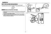
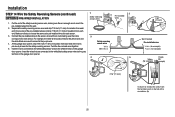
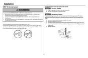
... if they are glowing steadily. Installation STEP 16 Aligning the safety reversing sensors The door will flash ten times. When the light beam is obstructed or misaligned while the door is power to the garage door opener. 2. The LEDs in both sensors will not close if the sensors have not... installed and aligned correctly. IF THE AMBER LED ON THE SENDING SENSOR IS NOT GLOWING: 1. Make sure there is closing, the door will reverse and the garage door opener lights will not close . 1. Make sure the sensor wire is not shorted/broken. 2. Make sure the sensor has been wired ...
... if they are glowing steadily. Installation STEP 16 Aligning the safety reversing sensors The door will flash ten times. When the light beam is obstructed or misaligned while the door is power to the garage door opener. 2. The LEDs in both sensors will not close if the sensors have not... installed and aligned correctly. IF THE AMBER LED ON THE SENDING SENSOR IS NOT GLOWING: 1. Make sure there is closing, the door will reverse and the garage door opener lights will not close . 1. Make sure the sensor wire is not shorted/broken. 2. Make sure the sensor has been wired ...


