
Configuration Guide
Page 5
... Routers 1-2 Features of the Cisco 12008 Router 1-3 Overview of the Cisco 12008 1-6 Router Enclosure 1-8 Cable-Management System 1-8 Card Cage Fan Tray 1-10 Power Supply Fan Tray 1-11 AC-Input and DC-Input Power Supplies 1-12 Operating Modes of the Power Supplies 1-14 Features of the Power Supplies 1-15 Characteristics of the Power Supplies 1-16 AC-Input Power Supply Faceplate 1-16 DC-Input Power Supply Faceplate 1-19 Table of...
... Routers 1-2 Features of the Cisco 12008 Router 1-3 Overview of the Cisco 12008 1-6 Router Enclosure 1-8 Cable-Management System 1-8 Card Cage Fan Tray 1-10 Power Supply Fan Tray 1-11 AC-Input and DC-Input Power Supplies 1-12 Operating Modes of the Power Supplies 1-14 Features of the Power Supplies 1-15 Characteristics of the Power Supplies 1-16 AC-Input Power Supply Faceplate 1-16 DC-Input Power Supply Faceplate 1-19 Table of...

Configuration Guide
Page 7
... 3-3 Removing Components from the Router 3-6 Removing Cards from the Upper Card Cage 3-6 Removing a Power Supply from the Router 3-9 Rack-Mounting the Cisco 12008 3-11 Reinstalling Components in the Router 3-14 Reinstalling the Cards in the Upper Card Cage 3-14 Reinstalling the Power Supplies in the Router 3-15 Connecting the Line Card Cables 3-17 Connecting Route Processor...
... 3-3 Removing Components from the Router 3-6 Removing Cards from the Upper Card Cage 3-6 Removing a Power Supply from the Router 3-9 Rack-Mounting the Cisco 12008 3-11 Reinstalling Components in the Router 3-14 Reinstalling the Cards in the Upper Card Cage 3-14 Reinstalling the Power Supplies in the Router 3-15 Connecting the Line Card Cables 3-17 Connecting Route Processor...

Configuration Guide
Page 8
... External Alarm Monitoring Facility 3-34 Connecting System Ground 3-38 Connecting Source Power to the Power Supplies 3-41 Connecting Source Power to an AC-Input Power Supply 3-42 Connecting Source Power to a DC-Input Power Supply 3-46 Starting the Cisco 12008 3-50 Observing System Startup and Performing a Basic Configuration 4-1 Sources of Cisco IOS Software 4-2 Checking Conditions Prior to System Startup 4-3 Starting the System...
... External Alarm Monitoring Facility 3-34 Connecting System Ground 3-38 Connecting Source Power to the Power Supplies 3-41 Connecting Source Power to an AC-Input Power Supply 3-42 Connecting Source Power to a DC-Input Power Supply 3-46 Starting the Cisco 12008 3-50 Observing System Startup and Performing a Basic Configuration 4-1 Sources of Cisco IOS Software 4-2 Checking Conditions Prior to System Startup 4-3 Starting the System...
Configuration Guide
Page 9
...RP 4-46 Installing and Removing a Flash Memory Card in a RP 4-47 Formatting a Flash Memory Card 4-49 Specifying a Cisco IOS Image for Booting the System 4-50 Console Commands Associated with Flash Memory Use 4-51 Enabling Booting from Flash Memory 4-53 ... System Status at Startup 5-2 Problem Solving Using a Subsystem Approach 5-4 Identifying Startup Problems 5-6 Normal System Startup Sequence 5-6 Power Supply Status LEDs 5-7 Troubleshooting the Power Subsystem 5-10 Troubleshooting the Processor Subsystem 5-12 Troubleshooting the RP 5-13 Troubleshooting the Line Cards 5-15 CSC Alarm Functions ...
...RP 4-46 Installing and Removing a Flash Memory Card in a RP 4-47 Formatting a Flash Memory Card 4-49 Specifying a Cisco IOS Image for Booting the System 4-50 Console Commands Associated with Flash Memory Use 4-51 Enabling Booting from Flash Memory 4-53 ... System Status at Startup 5-2 Problem Solving Using a Subsystem Approach 5-4 Identifying Startup Problems 5-6 Normal System Startup Sequence 5-6 Power Supply Status LEDs 5-7 Troubleshooting the Power Subsystem 5-10 Troubleshooting the Processor Subsystem 5-12 Troubleshooting the RP 5-13 Troubleshooting the Line Cards 5-15 CSC Alarm Functions ...

Configuration Guide
Page 10
... Cisco 12008 7-1 Cleaning the Air Filter 7-2 Installing and Removing a Blank Filler Panel 7-5 Adding, Removing, or Replacing an AC-Input Power Supply 7-7 Adding an AC-Input Power Supply 7-7 Removing an AC-Input Power Supply 7-11 Replacing an Existing AC-Input Power Supply 7-13 Verifying the Installation of an AC-Input Power Supply 7-15 Adding, Removing, or Replacing a DC-Input Power Supply 7-17 Adding a DC-Input Power Supply...
... Cisco 12008 7-1 Cleaning the Air Filter 7-2 Installing and Removing a Blank Filler Panel 7-5 Adding, Removing, or Replacing an AC-Input Power Supply 7-7 Adding an AC-Input Power Supply 7-7 Removing an AC-Input Power Supply 7-11 Replacing an Existing AC-Input Power Supply 7-13 Verifying the Installation of an AC-Input Power Supply 7-15 Adding, Removing, or Replacing a DC-Input Power Supply 7-17 Adding a DC-Input Power Supply...

Configuration Guide
Page 23
...; Cable-Management System • Card Cage Fan Tray • Power Supply Fan Tray • AC-Input and DC-Input Power Supplies • Upper Card Cage and Associated Components • Air Filter Assembly • Lower Card Cage and Associated Components • Power Distribution System in the Cisco 12008 • Cisco 12008 Environmental Monitoring Facility • System Specifications • Agency Approvals...
...; Cable-Management System • Card Cage Fan Tray • Power Supply Fan Tray • AC-Input and DC-Input Power Supplies • Upper Card Cage and Associated Components • Air Filter Assembly • Lower Card Cage and Associated Components • Power Distribution System in the Cisco 12008 • Cisco 12008 Environmental Monitoring Facility • System Specifications • Agency Approvals...

Configuration Guide
Page 26
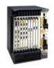
... Power supplies-One AC-input power supply or one DC-input power supply is installed in the system. 1-4 Cisco 12008 Gigabit Switch Router Installation and Configuration Guide You can remove or replace a power supply, without disrupting system operations, only if a second (redundant) unit of the Cisco 12008 Router Figure 1-1 Cisco 12008 ...Fail PLWINRECSAPRLYD Fan Fail H7689 Fail Enabled SFC Fail Enabled SFC GIGABIT ROUTE PROCESSOR CSC-8 CSC-8 The Cisco 12008 supports the following features: • Online insertion and removal (OIR) capability-This feature allows you to insert...
... Power supplies-One AC-input power supply or one DC-input power supply is installed in the system. 1-4 Cisco 12008 Gigabit Switch Router Installation and Configuration Guide You can remove or replace a power supply, without disrupting system operations, only if a second (redundant) unit of the Cisco 12008 Router Figure 1-1 Cisco 12008 ...Fail PLWINRECSAPRLYD Fan Fail H7689 Fail Enabled SFC Fail Enabled SFC GIGABIT ROUTE PROCESSOR CSC-8 CSC-8 The Cisco 12008 supports the following features: • Online insertion and removal (OIR) capability-This feature allows you to insert...

Configuration Guide
Page 27
...Any one of the units fails, the surviving power supply continues to operate to sustain normal router operations. In a system equipped with no disruption to system operations. Note The Cisco 12008 does not support a mixture of the router. Cisco 12000 series line cards-Any line card supported... CSC is either reinstalled or replaced by the Cisco 12008 router can be removed and replaced, but you must power down . Clock and scheduler card (CSC)-Also a required component, a CSC can be sustained. - Features of the Cisco 12008 Router The power supplies of both types are lost to the router...
...Any one of the units fails, the surviving power supply continues to operate to sustain normal router operations. In a system equipped with no disruption to system operations. Note The Cisco 12008 does not support a mixture of the router. Cisco 12000 series line cards-Any line card supported... CSC is either reinstalled or replaced by the Cisco 12008 router can be removed and replaced, but you must power down . Clock and scheduler card (CSC)-Also a required component, a CSC can be sustained. - Features of the Cisco 12008 Router The power supplies of both types are lost to the router...

Configuration Guide
Page 29
or DC-input power supplies (AC-input power supplies shown) Power supply fan tray Product Overview 1-7 Overview of the Cisco 12008 Figure 1-2 Major Components of the Cisco 12008 Router enclosure Cable-management tray H7691 EJECT SSLLOOTT--01 RESET AUX Alarm Alarm ACO/LT ACO/LT CONSOLE CriticaMl ajor Minor Alarms CriticaMl ajor Minor ...
or DC-input power supplies (AC-input power supplies shown) Power supply fan tray Product Overview 1-7 Overview of the Cisco 12008 Figure 1-2 Major Components of the Cisco 12008 Router enclosure Cable-management tray H7691 EJECT SSLLOOTT--01 RESET AUX Alarm Alarm ACO/LT ACO/LT CONSOLE CriticaMl ajor Minor Alarms CriticaMl ajor Minor ...

Configuration Guide
Page 33
.... If the increased fan speed does not alleviate the overtemperature condition in the section entitled "Cisco 12008 Environmental Monitoring Facility" on page 74. Power Supply Fan Tray The power supply fan tray is in the bottom of the Cisco 12008 router is described in greater detail in the affected board, the MBus module on the board shuts down...
.... If the increased fan speed does not alleviate the overtemperature condition in the section entitled "Cisco 12008 Environmental Monitoring Facility" on page 74. Power Supply Fan Tray The power supply fan tray is in the bottom of the Cisco 12008 router is described in greater detail in the affected board, the MBus module on the board shuts down...
Configuration Guide
Page 34
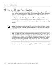
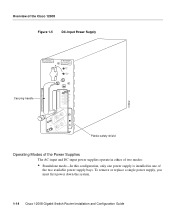
... power supply. Figure 1-4 shows an AC-input power supply; You can install one or two AC-input power supplies or one or two DC-input power supplies in the power supply bays located in the right side of the router enclosure (see Figure 1-2). Furthermore, you should not power the router with AC source power or DC source power. Figure 1-5 shows a DC-input power supply. 1-12 Cisco 12008...
... power supply. Figure 1-4 shows an AC-input power supply; You can install one or two AC-input power supplies or one or two DC-input power supplies in the power supply bays located in the right side of the router enclosure (see Figure 1-2). Furthermore, you should not power the router with AC source power or DC source power. Figure 1-5 shows a DC-input power supply. 1-12 Cisco 12008...
Configuration Guide
Page 35
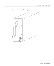
Figure 1-4 AC-Input Power Supply Overview of the Cisco 12008 0 INPUT 0K OUTPUT FAIL H10033 Product Overview 1-13
Figure 1-4 AC-Input Power Supply Overview of the Cisco 12008 0 INPUT 0K OUTPUT FAIL H10033 Product Overview 1-13
Configuration Guide
Page 36
... FAIL TER MIN ALS MA Y BE EN COM ER GIZ Carrying handle ED. Overview of the two available power supply bays. To remove or replace a single power supply, you must first power down the system. 1-14 Cisco 12008 Gigabit Switch Router Installation and Configuration Guide NC BER UHR NO EN DER ANS CHL USS E DEN HAU PTS...
... FAIL TER MIN ALS MA Y BE EN COM ER GIZ Carrying handle ED. Overview of the two available power supply bays. To remove or replace a single power supply, you must first power down the system. 1-14 Cisco 12008 Gigabit Switch Router Installation and Configuration Guide NC BER UHR NO EN DER ANS CHL USS E DEN HAU PTS...

Configuration Guide
Page 37
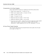
... an appropriate LED on all of the router circuit boards, including the RP. Product Overview 1-15 Overview of the Cisco 12008 • Redundant (1+1) mode-In this configuration, two power supplies are installed in the power supply bays, sharing the load current to provide required DC operating voltages to be installed in or removed from the router...
... an appropriate LED on all of the router circuit boards, including the RP. Product Overview 1-15 Overview of the Cisco 12008 • Redundant (1+1) mode-In this configuration, two power supplies are installed in the power supply bays, sharing the load current to provide required DC operating voltages to be installed in or removed from the router...
Configuration Guide
Page 38
... voltages with the following characteristics: • Width of power supply body-3.5 inches (8.97 cm) • Width of the AC-input power supply (see Figure 1-6). 1-16 Cisco 12008 Gigabit Switch Router Installation and Configuration Guide AC-Input Power Supply Faceplate This section describes the functional elements built into the faceplate of power supply faceplate-4.0 inches (10.26 cm) • Height-10...
... voltages with the following characteristics: • Width of power supply body-3.5 inches (8.97 cm) • Width of the AC-input power supply (see Figure 1-6). 1-16 Cisco 12008 Gigabit Switch Router Installation and Configuration Guide AC-Input Power Supply Faceplate This section describes the functional elements built into the faceplate of power supply faceplate-4.0 inches (10.26 cm) • Height-10...
Configuration Guide
Page 39
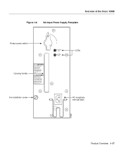
AC INPUT 0K OUTPUT FAIL LEDs tive installation screw ~ INPUT 200-240V 10 A 50/60 HZ 2000 W AC receptacle with bail latch H10031 Product Overview 1-17 ALL CONNECTIONS NEED TO BE REMOVED TO DE-ENERGIZE THE UNIT. Overview of the Cisco 12008 Figure 1-6 AC-Input Power Supply Faceplate Rotary power switch Carrying handle CAUTION THIS UNIT MAY HAVE MORE THAN ONE POWER SUPPLY CONNECTION. ACHTUNG DIESE EINHEIT HAT MEHR ALS EINEN NETZTEIL-ANSCHLUSS: ALLE VERBINDUNGEN MUSSEN ABGEZOGEN WERDEN, DAMIT DIE EINHEIT NICHT UNTER SPANNUNG STEHT.
AC INPUT 0K OUTPUT FAIL LEDs tive installation screw ~ INPUT 200-240V 10 A 50/60 HZ 2000 W AC receptacle with bail latch H10031 Product Overview 1-17 ALL CONNECTIONS NEED TO BE REMOVED TO DE-ENERGIZE THE UNIT. Overview of the Cisco 12008 Figure 1-6 AC-Input Power Supply Faceplate Rotary power switch Carrying handle CAUTION THIS UNIT MAY HAVE MORE THAN ONE POWER SUPPLY CONNECTION. ACHTUNG DIESE EINHEIT HAT MEHR ALS EINEN NETZTEIL-ANSCHLUSS: ALLE VERBINDUNGEN MUSSEN ABGEZOGEN WERDEN, DAMIT DIE EINHEIT NICHT UNTER SPANNUNG STEHT.

Configuration Guide
Page 40
... Chapter 2 in the ON (1) position. Overview of the AC power cord. AC-Input Power Supply LEDs The AC-input power supply faceplate incorporates two LEDs (see Figure 1-6) that prevents accidental or unintended removal of the Cisco 12008 Rotary Power Switch The rotary power switch on the power supply faceplate (see Figure 1-6) enables an external AC power source to be connected to the...
... Chapter 2 in the ON (1) position. Overview of the AC power cord. AC-Input Power Supply LEDs The AC-input power supply faceplate incorporates two LEDs (see Figure 1-6) that prevents accidental or unintended removal of the Cisco 12008 Rotary Power Switch The rotary power switch on the power supply faceplate (see Figure 1-6) enables an external AC power source to be connected to the...
Configuration Guide
Page 41
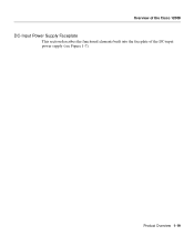
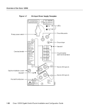
Overview of the Cisco 12008 DC-Input Power Supply Faceplate This section describes the functional elements built into the faceplate of the DC-input power supply (see Figure 1-7). Product Overview 1-19
Overview of the Cisco 12008 DC-Input Power Supply Faceplate This section describes the functional elements built into the faceplate of the DC-input power supply (see Figure 1-7). Product Overview 1-19
Configuration Guide
Page 42
... UNTER SPANNUNG STEHEN. Overview of the Cisco 12008 Figure 1-7 DC-Input Power Supply Faceplate THIS UNIT TO BE INSTALLED IN A RESTRICTED ACCESS AREA IN ACCORDANCE WITH THE NEC OR THE AUTHORITY HAVING JURISDICTION Rotary power switch CAUTION THIS UNIT MAY HAVE MORE THAN ONE POWER SUPPLY CONNECTION. INPUT 0K OUTPUT FAIL LEDs ...NC Circuit breaker alarm terminal block NO Source DC lugs (2) INPUT: -48/-60V 39 A 1580 VA Source DC lugs (2) H10030 1-20 Cisco 12008 Gigabit Switch Router Installation and Configuration Guide ALL CONNECTIONS NEED TO BE REMOVED TO DE-ENERGIZE THE UNIT.
... UNTER SPANNUNG STEHEN. Overview of the Cisco 12008 Figure 1-7 DC-Input Power Supply Faceplate THIS UNIT TO BE INSTALLED IN A RESTRICTED ACCESS AREA IN ACCORDANCE WITH THE NEC OR THE AUTHORITY HAVING JURISDICTION Rotary power switch CAUTION THIS UNIT MAY HAVE MORE THAN ONE POWER SUPPLY CONNECTION. INPUT 0K OUTPUT FAIL LEDs ...NC Circuit breaker alarm terminal block NO Source DC lugs (2) INPUT: -48/-60V 39 A 1580 VA Source DC lugs (2) H10030 1-20 Cisco 12008 Gigabit Switch Router Installation and Configuration Guide ALL CONNECTIONS NEED TO BE REMOVED TO DE-ENERGIZE THE UNIT.

Configuration Guide
Page 43
... remain unaffected. Product Overview 1-21 Overview of the Cisco 12008 Rotary Power Switch The rotary power switch on the DC-input power supply performs the same functions as those described in the power supply, this serious fault condition. When the power supply circuit breaker is tripped by the rotary power switch on the DCinput power supply incorporates an auxiliary switch that a circuit breaker...
... remain unaffected. Product Overview 1-21 Overview of the Cisco 12008 Rotary Power Switch The rotary power switch on the DC-input power supply performs the same functions as those described in the power supply, this serious fault condition. When the power supply circuit breaker is tripped by the rotary power switch on the DCinput power supply incorporates an auxiliary switch that a circuit breaker...


