
Configuration Guide
Page 13
... Router 6-1 Powering Down the Router 6-2 Removing and Installing the Front Door on Cisco 12006 and Cisco 12406 Enhanced Series Router 6-3 Cleaning or Replacing the Air Filters 6-7 Removing and Replacing the Blower Module 6-9 Troubleshooting the Blower Installation 6-12 Removing and Replacing AC and DC Power Subsystem Components 6-13 Installation Guidelines 6-14 Power Supply and PDU Compatibility...
... Router 6-1 Powering Down the Router 6-2 Removing and Installing the Front Door on Cisco 12006 and Cisco 12406 Enhanced Series Router 6-3 Cleaning or Replacing the Air Filters 6-7 Removing and Replacing the Blower Module 6-9 Troubleshooting the Blower Installation 6-12 Removing and Replacing AC and DC Power Subsystem Components 6-13 Installation Guidelines 6-14 Power Supply and PDU Compatibility...
Configuration Guide
Page 66
... sales representative for redundant operation) Caution To ensure that is shipped from the factory as an FRU. Note Cisco 12006 and Cisco 12406 routers operating from a DC power source, and vice versa. AC Power Subsystem The AC power subsystem consists of the following system components:...configuration complies with the required power budgets, use the on the chassis rear panel. (See Figure 1-2 and Figure 1-12.) 1-38 Cisco 12006 and Cisco 12406 Router Installation and Configuration Guide OL-11497-03 For more information about this conversion process, see Chapter 6, "Maintaining the ...
... sales representative for redundant operation) Caution To ensure that is shipped from the factory as an FRU. Note Cisco 12006 and Cisco 12406 routers operating from a DC power source, and vice versa. AC Power Subsystem The AC power subsystem consists of the following system components:...configuration complies with the required power budgets, use the on the chassis rear panel. (See Figure 1-2 and Figure 1-12.) 1-38 Cisco 12006 and Cisco 12406 Router Installation and Configuration Guide OL-11497-03 For more information about this conversion process, see Chapter 6, "Maintaining the ...

Configuration Guide
Page 92
... of the rack must be at least 24 inches (61 cm) of clearance in front of the chassis is already installed 2-12 Cisco 12006 and Cisco 12406 Router Installation and Configuration Guide OL-11497-03 Use appropriate strain-relief methods to protect cables and equipment connections. • Install... for source AC or DC power, grounding, and network interface cables. • For the actual installation, allow sufficient space to overhead brackets. • Do not route cables in such a way as 205 pounds (93 kg). You will accommodate four Cisco 12006 and Cisco 12406 Routers. You will need...
... of the rack must be at least 24 inches (61 cm) of clearance in front of the chassis is already installed 2-12 Cisco 12006 and Cisco 12406 Router Installation and Configuration Guide OL-11497-03 Use appropriate strain-relief methods to protect cables and equipment connections. • Install... for source AC or DC power, grounding, and network interface cables. • For the actual installation, allow sufficient space to overhead brackets. • Do not route cables in such a way as 205 pounds (93 kg). You will accommodate four Cisco 12006 and Cisco 12406 Routers. You will need...

Configuration Guide
Page 290
The Output Power OK and Input Power OK indicators on page 6-35. 6-46 Cisco 12006 and Cisco 12406 Router Installation and Configuration Guide OL-11497-03 If the indicators do not light, see the "Troubleshooting the DC Power Supply Installation" section on the power supplies should light. Removing and Replacing a DC PDU Chapter 6 Maintaining the Router Step 12 Power on the power supplies.
The Output Power OK and Input Power OK indicators on page 6-35. 6-46 Cisco 12006 and Cisco 12406 Router Installation and Configuration Guide OL-11497-03 If the indicators do not light, see the "Troubleshooting the DC Power Supply Installation" section on the power supplies should light. Removing and Replacing a DC PDU Chapter 6 Maintaining the Router Step 12 Power on the power supplies.
Configuration Guide
Page 333
... in a rack 3-8 lifting (caution) 2-5 outer dimensions 2-11 overview 1-7 to 1-9 removing and installing 6-68 to 6-77 width A-2 Cisco 12006 Series electrical specifications AC-input power supply A-3 DC-input PEM A-4 environmental specifications A-5 physical specifications A-2 codes, electrical 1-46, 2-4, 2-16 commands associated with Flash memory use 3-69 boot ... 3-61, 4-7, 4-11 squeeze 3-71 compliance information router model number location A-6 config-register command 3-68, 3-72, 4-6, 4-8, 4-12, 4-13 OL-11497-03 Cisco 12006 and Cisco 12406 Router Installation and Configuration Guide IN-3
... in a rack 3-8 lifting (caution) 2-5 outer dimensions 2-11 overview 1-7 to 1-9 removing and installing 6-68 to 6-77 width A-2 Cisco 12006 Series electrical specifications AC-input power supply A-3 DC-input PEM A-4 environmental specifications A-5 physical specifications A-2 codes, electrical 1-46, 2-4, 2-16 commands associated with Flash memory use 3-69 boot ... 3-61, 4-7, 4-11 squeeze 3-71 compliance information router model number location A-6 config-register command 3-68, 3-72, 4-6, 4-8, 4-12, 4-13 OL-11497-03 Cisco 12006 and Cisco 12406 Router Installation and Configuration Guide IN-3

Configuration Guide
Page 334
... CSC 10-Gbps 1-12, A-7 2.5-Gbps 1-12, A-7 ejector levers 6-60 label identifying switch fabric type 1-12 removing and installing (figure) 6-58 procedure 6-57 to 6-61 verifying operation of replacement CSC 6-60 current rating input AC-input power supply A-3 DC-input PEM A-4 output AC-input power supply A-3 DC-input PEM A-4 IN-4 Cisco 12006 and Cisco 12406 Router Installation and Configuration...
... CSC 10-Gbps 1-12, A-7 2.5-Gbps 1-12, A-7 ejector levers 6-60 label identifying switch fabric type 1-12 removing and installing (figure) 6-58 procedure 6-57 to 6-61 verifying operation of replacement CSC 6-60 current rating input AC-input power supply A-3 DC-input PEM A-4 output AC-input power supply A-3 DC-input PEM A-4 IN-4 Cisco 12006 and Cisco 12406 Router Installation and Configuration...

Configuration Guide
Page 337
...figure) 1-18 soft reset switch function 1-22 usage (caution) 1-23 SRAM 1-20 I IEEE 802.3u specifications 3-29 initialize command 4-12 inservice testing 5-1 interface parameters, configuring 3-58, 3-61 interrupting system with Break key 4-10 L laser safety information 2-5 LEDs AC-...DC-input PEM 1-46 device or port activity GRP 1-21 PRP 1-30 GRP alphanumeric LED displays 1-21, 3-41 device or port activity 3-43 device or port activity (figure) 3-43 PRP alphanumeric LED displays 1-30, 3-41 device or port activity 1-30 device or port activity (figure) 3-45 OL-11497-03 Cisco 12006 and Cisco 12406...
...figure) 1-18 soft reset switch function 1-22 usage (caution) 1-23 SRAM 1-20 I IEEE 802.3u specifications 3-29 initialize command 4-12 inservice testing 5-1 interface parameters, configuring 3-58, 3-61 interrupting system with Break key 4-10 L laser safety information 2-5 LEDs AC-...DC-input PEM 1-46 device or port activity GRP 1-21 PRP 1-30 GRP alphanumeric LED displays 1-21, 3-41 device or port activity 3-43 device or port activity (figure) 3-43 PRP alphanumeric LED displays 1-30, 3-41 device or port activity 1-30 device or port activity (figure) 3-45 OL-11497-03 Cisco 12006 and Cisco 12406...

Configuration Guide
Page 342
... power subsystem 4-17, 4-23 to 4-26 blower module 4-35, 4-36 boot process 4-16 cooling subsystem 4-35 damaged AC power cord 4-24 damaged DC power wiring 4-27 DC-input power subsystem 4-26 to 4-28 environmental shutdown 4-36 field diagnostics 5-1 inservice testing 5-1 line cards 4-31 power problems 4-15 power subsystem 4-23 ... power source See UPS UPS 2-14, 2-16 using boot flash command caution 3-48 using handles for lifting (caution) 2-5 V voltage input AC-input power supply A-3 DC-input PEM A-4 output IN-12 Cisco 12006 and Cisco 12406 Router Installation and Configuration Guide OL-11497-03
... power subsystem 4-17, 4-23 to 4-26 blower module 4-35, 4-36 boot process 4-16 cooling subsystem 4-35 damaged AC power cord 4-24 damaged DC power wiring 4-27 DC-input power subsystem 4-26 to 4-28 environmental shutdown 4-36 field diagnostics 5-1 inservice testing 5-1 line cards 4-31 power problems 4-15 power subsystem 4-23 ... power source See UPS UPS 2-14, 2-16 using boot flash command caution 3-48 using handles for lifting (caution) 2-5 V voltage input AC-input power supply A-3 DC-input PEM A-4 output IN-12 Cisco 12006 and Cisco 12406 Router Installation and Configuration Guide OL-11497-03
Chassis Replacement Instructions
Page 12
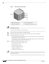
...conditions are true: • LEDs on the faceplates of the power modules. To remove power from the terminal connector block on the DC PDU. (See Figure 9.) Verify that all facility power source circuit breakers for power cables connected to verify that the blowers are ...LEDs are off • All alarm card LEDs are off • All RP and line card LEDs are off. Cisco 12006 and Cisco 12406 Router Chassis Replacement Instructions 12 78-16109-01 Figure 9 PDU DC Power Connector Block POWER A 4 +1 2 GND 3 57993 1 Negative Terminal Port 2 Positive Terminal Port 3 Ground Terminal...
...conditions are true: • LEDs on the faceplates of the power modules. To remove power from the terminal connector block on the DC PDU. (See Figure 9.) Verify that all facility power source circuit breakers for power cables connected to verify that the blowers are ...LEDs are off • All alarm card LEDs are off • All RP and line card LEDs are off. Cisco 12006 and Cisco 12406 Router Chassis Replacement Instructions 12 78-16109-01 Figure 9 PDU DC Power Connector Block POWER A 4 +1 2 GND 3 57993 1 Negative Terminal Port 2 Positive Terminal Port 3 Ground Terminal...

Chassis Replacement Instructions
Page 29
...signal-encoded beam of light accurately from the rightmost port to the leftmost port (on line cards with the DC Power Distribution Unit 78-16109-01 Cisco 12006 and Cisco 12406 Router Chassis Replacement Instructions 29 Note To comply with a 3/16-inch flat-blade screwdriver. Proceeding from one end...any kinks or sharp bends in the interface cable. Reconnecting Line Card Network Interface Cables To reconnect network interface cables to a line card, see Figure 12 and follow these steps: Step 1 Step 2 Step 3 Step 4 Step 5 Step 6 Step 7 Attach an ESD-preventive wrist strap to your ...
...signal-encoded beam of light accurately from the rightmost port to the leftmost port (on line cards with the DC Power Distribution Unit 78-16109-01 Cisco 12006 and Cisco 12406 Router Chassis Replacement Instructions 29 Note To comply with a 3/16-inch flat-blade screwdriver. Proceeding from one end...any kinks or sharp bends in the interface cable. Reconnecting Line Card Network Interface Cables To reconnect network interface cables to a line card, see Figure 12 and follow these steps: Step 1 Step 2 Step 3 Step 4 Step 5 Step 6 Step 7 Attach an ESD-preventive wrist strap to your ...